


600/1000V PVC Insulated Cable to IEC 60502-1 Standard
The 600/1000V PVC Insulated Low Voltage Power Cable is designed for reliable power transmission in low-voltage electrical systems. Manufactured with high-quality copper or aluminum conductors and PVC insulation, this cable provides stable electrical performance, good flexibility, and long service life. The PVC insulation offers effective protection against moisture, abrasion, oils, and common chemicals, making the cable suitable for both indoor and outdoor installations.
Rated at 600/1000 volts, the cable ensures safe and efficient power distribution under normal operating conditions. Its robust insulation structure supports consistent current flow while maintaining electrical safety. The cable is easy to install, route, and terminate, making it a practical solution for residential, commercial, and industrial power networks. With dependable insulation performance and mechanical durability, this low voltage power cable meets the demands of everyday electrical infrastructure.
- Standard IEC 60502-1
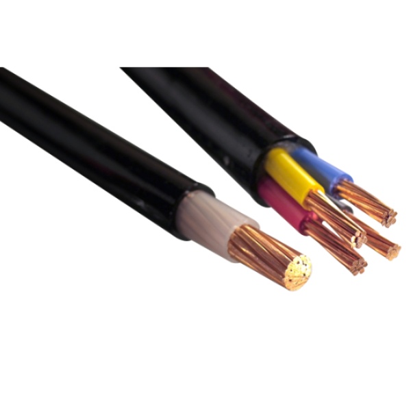
Construction
Technical Specifications
Quality Control
Application
Construction
600/1000V, PVC Insulated Low Voltage Power Cable
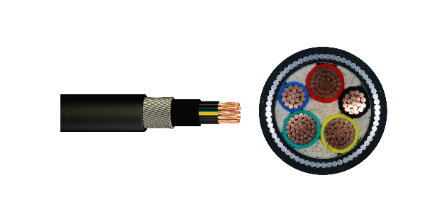
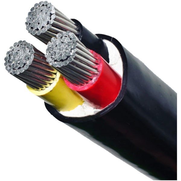
Conductor
Copper or Aluminium conductor,round standed or Compacted,Class2 to IEC 60228,BS EN 60228.For smaller sizes,solid conductor, Class 1 as per IEC 60228, BS EN 60228 can also be supplied upon request.
Insulation
PVC Insulation material and thickness shall be as per IEC 60502-1, PVC material shall be Type A as per IEC 60502-1
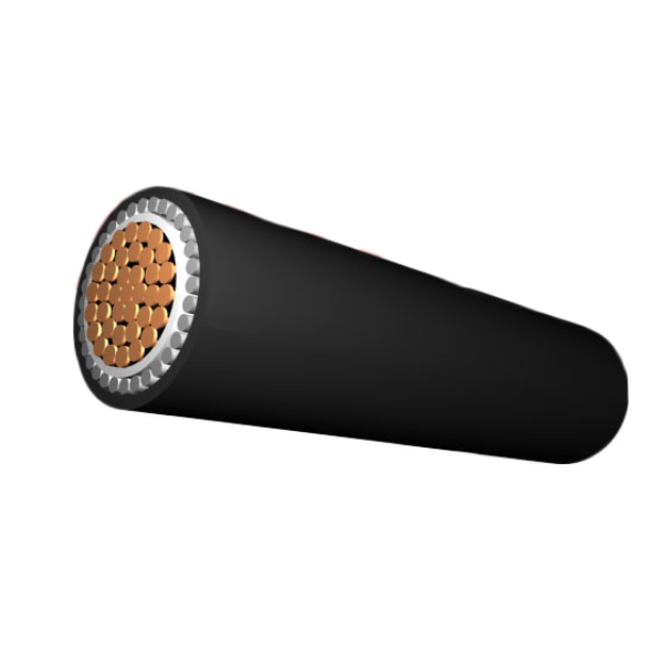
Inner Covering
Inner sheath shall be of extruded PVC Type ST1/ST2 as per IEC 60502-1,Polyethylene type ST3/ST7, Halogen free compound ST8, Polychloroprene, chlorosulfonated polyethylene or similar polymers, type SE1 are also available on request.lapped is also applicable.
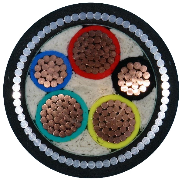
Armour
Aluminum/galvanized steel/steel wires applied helically over the Inner Covering as per IEC 60502-1, or double aluminum/steel tapes and copper/tinned copper wire can also be manufactured upon request.
Outer Sheath
Outer sheath shall be of extruded PVC Type ST1/ST2 as per IEC 60502-1,Polyethylene type ST3/ST7, Halogen free compound ST8, type SE1 are also available on request.
Fire Performance of Cable Sheaths
Cables can be supplied with special flame retardant PVC outer sheath to comply with the flame test requirements of IEC 60332-3-22, IEC 60332-3-23 and IEC 60332-3-24, Halogen Free material comply to IEC60754-1/2 and IEC 60684-2.
Color Code (1)
1 Core : Red or Black
2 Cores: Red, Black
3 Cores: Red, Yellow, Blue
4 Cores: Red, Yellow, Blue, Black
5 Cores: Red, Yellow, Blue, Black, Green
Above 5 Cores: Black Cores with White numerals
2 Cores: Red, Black
3 Cores: Red, Yellow, Blue
4 Cores: Red, Yellow, Blue, Black
5 Cores: Red, Yellow, Blue, Black, Green
Above 5 Cores: Black Cores with White numerals
Color Code (2)
1 Core : Brown or Blue
2 Cores : Brown, Blue
3 Cores : Brown, Black, Grey
4 Cores : Blue, Brown, Black, Grey
5 Cores : Green/Yellow, Blue, Brown, Black, Grey
Above 5 Cores: Black Cores with White numerals
Other colors can be manufactured upon request.
2 Cores : Brown, Blue
3 Cores : Brown, Black, Grey
4 Cores : Blue, Brown, Black, Grey
5 Cores : Green/Yellow, Blue, Brown, Black, Grey
Above 5 Cores: Black Cores with White numerals
Other colors can be manufactured upon request.
Technical Specifications
600/1000V PVC Insulated Cable to IEC 60502-1 Standard
Single core(unarmoured)
Two cores(unarmoured)
Three cores(unarmoured)
Four cores(unarmoured)
Three cores+1(unarmoured)
Multi-cores(unarmoured)
Single core(Galvanized steel wire armoured)
Two cores(Galvanized steel wire armoured)
Three cores(Galvanized steel wire armoured)
Three cores+Earth core(Galvanized steel wire armoured)
Four cores(Galvanized steel wire armoured)
| Nominal Cross Section | Diameter of Conductor (Approx.) | Nominal Insulation Thickness | Nominal Sheath Thickness | Overall Diameter (Approx.) |
| mm² | mm | mm | mm | mm |
| 1 x 4 | 2.3 | 1 | 1.4 | 7.1 |
| 1 x 6 | 2.8 | 1 | 1.4 | 7.6 |
| 1 x 10 | 3.6 | 1 | 1.4 | 8.4 |
| 1 x 16 | 4.5 | 1 | 1.4 | 9.3 |
| 1 x 25 | 5.6 | 1.2 | 1.4 | 10.8 |
| 1 x 35 | 6.7 | 1.2 | 1.4 | 11.9 |
| 1 x 50 | 8 | 1.4 | 1.4 | 13.6 |
| 1 x 70 | 9.4 | 1.4 | 1.4 | 15.1 |
| 1 x 95 | 11 | 1.6 | 1.5 | 17.2 |
| 1 x 120 | 12.4 | 1.6 | 1.5 | 18.7 |
| 1 x 150 | 13.8 | 1.8 | 1.6 | 20.6 |
| 1 x 185 | 15.3 | 2 | 1.7 | 22.7 |
| 1 x 240 | 17.5 | 2.2 | 1.8 | 25.4 |
| 1 x 300 | 19.5 | 2.4 | 1.9 | 28 |
| 1 x 400 | 22.6 | 2.6 | 2 | 31.7 |
| 1 x 500 | 25.2 | 2.8 | 2.1 | 35 |
| 1 x 630 | 28.3 | 2.8 | 2.2 | 38.3 |
| Nominal Cross Section | Diameter of Conductor (Approx.) | Nominal Insulation Thickness | Nominal Sheath Thickness | Overall Diameter (Approx.) |
| mm² | mm | mm | mm | mm |
| 2 x 1.5 | 1.4 | 0.8 | 1.8 | 9.6 |
| 2 x 2.5 | 1.8 | 0.8 | 1.8 | 10.4 |
| 2 x 4 | 2.3 | 1 | 1.8 | 12.2 |
| 2 x 6 | 2.8 | 1 | 1.8 | 13.2 |
| 2 x 10 | 3.6 | 1 | 1.8 | 14.8 |
| 2 x 16 | 4.5 | 1 | 1.8 | 16.6 |
| 2 x 25 | 5.6 | 1.2 | 1.8 | 19.6 |
| 2 x 35 | 6.7 | 1.2 | 1.8 | 21.8 |
| 2 x 50 | 8 | 1.4 | 1.8 | 25.2 |
| 2 x 70 | 9.4 | 1.4 | 1.9 | 28.1 |
| 2 x 95 | 11 | 1.6 | 2 | 32.4 |
| 2 x 120 | 12.4 | 1.6 | 2.1 | 35.4 |
| 2 x 150 | 13.8 | 1.8 | 2.2 | 39.2 |
| 2 x 185 | 15.3 | 2 | 2.4 | 43.3 |
| 2 x 240 | 17.5 | 2.2 | 2.5 | 48.9 |
| 2 x 300 | 19.5 | 2.4 | 2.7 | 54 |
| 2 x 400 | 22.6 | 2.6 | 2.9 | 61.5 |
| Nominal Cross Section | Diameter of Conductor (Approx.) | Nominal Insulation Thickness | Nominal Sheath Thickness | Overall Diameter (Approx.) |
| mm² | mm | mm | mm | mm |
| 3 x 1.5 | 1.4 | 0.8 | 1.8 | 10.1 |
| 3 x 2.5 | 1.8 | 0.8 | 1.8 | 10.9 |
| 3 x 4 | 2.3 | 1 | 1.8 | 12.9 |
| 3 x 6 | 2.8 | 1 | 1.8 | 13.9 |
| 3 x 10 | 3.6 | 1 | 1.8 | 15.7 |
| 3 x 16 | 4.5 | 1 | 1.8 | 17.6 |
| 3 x 25 | 5.6 | 1.2 | 1.8 | 20.8 |
| 3 x 35 | 6.7 | 1.2 | 1.8 | 23.2 |
| 3 x 50 | 8 | 1.4 | 1.8 | 26.9 |
| 3 x 70 | 9.4 | 1.4 | 1.9 | 30.1 |
| 3 x 95 | 11 | 1.6 | 2.1 | 34.7 |
| 3 x 120 | 12.4 | 1.6 | 2.2 | 38 |
| 3 x 150 | 13.8 | 1.8 | 2.3 | 42.1 |
| 3 x 185 | 15.3 | 2 | 2.5 | 46.5 |
| 3 x 240 | 17.5 | 2.2 | 2.7 | 52.5 |
| 3 x 300 | 19.5 | 2.4 | 2.8 | 58 |
| 3 x 400 | 22.6 | 2.6 | 3.1 | 66.1 |
| Nominal Cross Section | Diameter of Conductor (Approx.) | Nominal Insulation Thickness | Nominal Sheath Thickness | Overall Diameter (Approx.) |
| mm² | mm | mm | mm | mm |
| 4 x 1.5 | 1.4 | 0.8 | 1.8 | 10.8 |
| 4 x 2.5 | 1.8 | 0.8 | 1.8 | 11.8 |
| 4 x 4 | 2.3 | 1 | 1.8 | 14 |
| 4 x 6 | 2.8 | 1 | 1.8 | 15.2 |
| 4 x 10 | 3.6 | 1 | 1.8 | 17.1 |
| 4 x 16 | 4.5 | 1 | 1.8 | 19.3 |
| 4 x 25 | 5.6 | 1.2 | 1.8 | 22.9 |
| 4 x 35 | 6.7 | 1.2 | 1.8 | 25.6 |
| 4 x 50 | 8 | 1.4 | 1.9 | 29.9 |
| 4 x 70 | 9.4 | 1.4 | 2 | 33.5 |
| 4 x 95 | 11 | 1.6 | 2.2 | 38.7 |
| 4 x 120 | 12.4 | 1.6 | 2.3 | 42.3 |
| 4 x 150 | 13.8 | 1.8 | 2.5 | 46.9 |
| 4 x 185 | 15.3 | 2 | 2.6 | 51.9 |
| 4 x 240 | 17.5 | 2.2 | 2.9 | 58.6 |
| 4 x 300 | 19.5 | 2.4 | 3.1 | 64.8 |
| 4 x 400 | 22.6 | 2.6 | 3.3 | 73.8 |
| Nominal Cross Section | Diameter of Conductor (Approx.) | Nominal Insulation Thickness | Nominal Sheath Thickness | Overall Diameter (Approx.) | ||
| mm² | (3)mm | (1)mm | (3)mm | (1)mm | mm | mm |
| 3 x 16/10 | 4.5 | 3.6 | 1 | 1 | 1.8 | 19 |
| 3 x 25/16 | 5.6 | 4.5 | 1.2 | 1 | 1.8 | 22.6 |
| 3 x 35/16 | 6.7 | 4.5 | 1.2 | 1 | 1.8 | 25.3 |
| 3 x 50/25 | 8 | 5.6 | 1.4 | 1.2 | 1.9 | 29.6 |
| 3 x 70/35 | 9.4 | 6.7 | 1.4 | 1.2 | 2 | 33.2 |
| 3 x 95/50 | 11 | 8 | 1.6 | 1.4 | 2.2 | 38.4 |
| 3 x 120/70 | 12.4 | 9.4 | 1.6 | 1.4 | 2.3 | 42 |
| 3 x 150/70 | 13.8 | 9.4 | 1.8 | 1.4 | 2.5 | 46.6 |
| 3 x 185/95 | 15.3 | 11 | 2 | 1.6 | 2.6 | 51.6 |
| 3 x 240/120 | 17.5 | 12.4 | 2.2 | 1.6 | 2.9 | 58.3 |
| 3 x 300/150 | 19.5 | 13.8 | 2.4 | 1.8 | 3.1 | 64.5 |
| 3 x 400/185 | 22.6 | 15.3 | 2.6 | 2 | 3.3 | 73.5 |
| Nominal Cross Section | Diameter of Conductor (Approx.) | Nominal Insulation Thickness | Nominal Sheath Thickness | Overall Diameter (Approx.) |
| mm² | mm | mm | mm | mm |
| 5 x 1.5 | 1.4 | 0.8 | 1.8 | 11.7 |
| 7 x 1.5 | 1.4 | 0.8 | 1.8 | 12.6 |
| 10 x 1.5 | 1.4 | 0.8 | 1.8 | 15.6 |
| 12 x 1.5 | 1.4 | 0.8 | 1.8 | 16.1 |
| 14 x 1.5 | 1.4 | 0.8 | 1.8 | 16.8 |
| 19 x 1.5 | 1.4 | 0.8 | 1.8 | 18.6 |
| 21 x 1.5 | 1.4 | 0.8 | 1.8 | 19.5 |
| 24 x 1.5 | 1.4 | 0.8 | 1.8 | 21.6 |
| 30 x 1.5 | 1.4 | 0.8 | 1.8 | 22.8 |
| 40 x 1.5 | 1.4 | 0.8 | 1.8 | 27.7 |
| 48 x 1.5 | 1.4 | 0.8 | 1.9 | 28.2 |
| 61 x 1.5 | 1.4 | 0.8 | 1.9 | 30.9 |
| 5 x 2.5 | 1.8 | 0.8 | 1.8 | 12.8 |
| 7 x 2.5 | 1.8 | 0.8 | 1.8 | 13.8 |
| 10 x 2.5 | 1.8 | 0.8 | 1.8 | 17.2 |
| 12 x 2.5 | 1.8 | 0.8 | 1.8 | 17.7 |
| 14 x 2.5 | 1.8 | 0.8 | 1.8 | 18.6 |
| 19 x 2.5 | 1.8 | 0.8 | 1.8 | 20.6 |
| 21 x 2.5 | 1.8 | 0.8 | 1.8 | 21.6 |
| 24 x 2.5 | 1.8 | 0.8 | 1.8 | 24 |
| 30 x 2.5 | 1.8 | 0.8 | 1.8 | 25.4 |
| 40 x 2.5 | 1.8 | 0.8 | 2 | 31.1 |
| 48 x 2.5 | 1.8 | 0.8 | 2 | 31.7 |
| 61 x 2.5 | 1.8 | 0.8 | 2.1 | 34.7 |
| Nominal Cross Section |
Diameter of Conductor (Approx.) |
Nominal Insulation thickness |
Nominal Inner Covering thickness |
Nominal Alum Wire dia. |
Nominal Sheath thickness |
Overall Diameter (Approx.) |
| mm² | mm | mm | mm | mm | mm | mm |
| 1 x 4 | 2.3 | 1 | 1 | 0.8 | 1.8 | 11.5 |
| 1 x 6 | 2.8 | 1 | 1 | 0.8 | 1.8 | 12 |
| 1 x 10 | 3.6 | 1 | 1 | 0.8 | 1.8 | 12.8 |
| 1 x 16 | 4.5 | 1 | 1 | 0.8 | 1.8 | 13.7 |
| 1 x 25 | 5.6 | 1.2 | 1 | 0.8 | 1.8 | 15.2 |
| 1 x 35 | 6.7 | 1.2 | 1 | 1.25 | 1.8 | 17.2 |
| 1 x 50 | 8 | 1.4 | 1 | 1.25 | 1.8 | 18.9 |
| 1 x 70 | 9.4 | 1.4 | 1 | 1.25 | 1.8 | 20.3 |
| 1 x 95 | 11 | 1.6 | 1 | 1.6 | 1.8 | 23 |
| 1 x 120 | 12.4 | 1.6 | 1 | 1.6 | 1.8 | 24.4 |
| 1 x 150 | 13.8 | 1.8 | 1 | 1.6 | 1.8 | 26.2 |
| 1 x 185 | 15.3 | 2 | 1 | 1.6 | 1.9 | 28.2 |
| 1 x 240 | 17.5 | 2.2 | 1 | 1.6 | 1.9 | 31 |
| 1 x 300 | 19.5 | 2.4 | 1 | 2 | 2.1 | 34.4 |
| 1 x 400 | 22.6 | 2.6 | 1.2 | 2 | 2.2 | 38.6 |
| 1 x 500 | 25.2 | 2.8 | 1.2 | 2 | 2.3 | 41.8 |
| 1 x 630 | 28.3 | 2.8 | 1.2 | 2.5 | 2.4 | 46.2 |
| Nominal Cross Section |
Diameter of Conductor (Approx.) |
Nominal Insulation thickness |
Nominal Inner Covering thickness |
Nominal Alum Wire dia. |
Nominal Sheath thickness |
Overall Diameter (Approx.) |
| mm² | mm | mm | mm | mm | mm | mm |
| 2 x 2.5 | 1.8 | 0.8 | 1 | 0.8 | 1.8 | 14 |
| 2 x 4 | 2.3 | 1 | 1 | 1.25 | 1.8 | 16.7 |
| 2 x 6 | 2.8 | 1 | 1 | 1.25 | 1.8 | 17.7 |
| 2 x 10 | 3.6 | 1 | 1 | 1.25 | 1.8 | 19.3 |
| 2 x 16 | 4.5 | 1 | 1 | 1.25 | 1.8 | 21.1 |
| 2 x 25 | 5.6 | 1.2 | 1 | 1.6 | 1.8 | 24.8 |
| 2 x 35 | 6.7 | 1.2 | 1 | 1.6 | 1.8 | 27 |
| 2 x 50 | 8 | 1.4 | 1 | 1.6 | 1.9 | 30.7 |
| 2 x 70 | 9.4 | 1.4 | 1 | 2 | 2.1 | 34.5 |
| 2 x 95 | 11 | 1.6 | 1.2 | 2 | 2.2 | 39.2 |
| 2 x 120 | 12.4 | 1.6 | 1.2 | 2 | 2.3 | 42.2 |
| 2 x 150 | 13.8 | 1.8 | 1.2 | 2.5 | 2.5 | 47.2 |
| 2 x 185 | 15.3 | 2 | 1.4 | 2.5 | 2.6 | 51.6 |
| 2 x 240 | 17.5 | 2.2 | 1.4 | 2.5 | 2.8 | 57.2 |
| 2 x 300 | 19.5 | 2.4 | 1.6 | 2.5 | 3 | 62.8 |
| 2 x 400 | 22.6 | 2.6 | 1.6 | 2.5 | 3.2 | 70.3 |
| Nominal Cross Section |
Diameter of Conductor (Approx.) |
Nominal Insulation thickness |
Nominal Inner Covering thickness |
Nominal Alum Wire dia. |
Nominal Sheath thickness |
Overall Diameter (Approx.) |
| mm² | mm | mm | mm | mm | mm | mm |
| 3 x 2.5 | 1.8 | 0.8 | 1 | 0.8 | 1.8 | 14.5 |
| 3 x 4 | 2.3 | 1 | 1 | 1.25 | 1.8 | 17.4 |
| 3 x 6 | 2.8 | 1 | 1 | 1.25 | 1.8 | 18.4 |
| 3 x 10 | 3.6 | 1 | 1 | 1.25 | 1.8 | 20.2 |
| 3 x 16 | 4.5 | 1 | 1 | 1.6 | 1.8 | 22.8 |
| 3 x 25 | 5.6 | 1.2 | 1 | 1.6 | 1.8 | 26 |
| 3 x 35 | 6.7 | 1.2 | 1 | 1.6 | 1.9 | 28.5 |
| 3 x 50 | 8 | 1.4 | 1 | 2 | 2 | 33.3 |
| 3 x 70 | 9.4 | 1.4 | 1.2 | 2 | 2.1 | 37 |
| 3 x 95 | 11 | 1.6 | 1.2 | 2 | 2.3 | 41.6 |
| 3 x 120 | 12.4 | 1.6 | 1.2 | 2.5 | 2.4 | 45.9 |
| 3 x 150 | 13.8 | 1.8 | 1.4 | 2.5 | 2.6 | 50.4 |
| 3 x 185 | 15.3 | 2 | 1.4 | 2.5 | 2.7 | 54.8 |
| 3 x 240 | 17.5 | 2.2 | 1.5 | 2.5 | 2.9 | 61.2 |
| 3 x 300 | 19.5 | 2.4 | 1.6 | 2.5 | 3.1 | 66.8 |
| 3 x 400 | 22.6 | 2.8 | 1.6 | 3.15 | 3.4 | 76.7 |
| 3 x 500 | 25.2 | 2.8 | 1.8 | 3.15 | 3.7 | 83.6 |
| Nominal Cross Section |
Diameter of Conductor (Approx.) |
Nominal Insulation thickness |
Nominal Inner Covering thickness |
Nominal Steel Wire dia. |
Nominal Sheath thickness |
Overall Diameter (Approx.) |
||
| mm² | mm | mm | mm | mm | mm | mm | mm | mm |
| 3 x 10/6 | 3.6 | 2.8 | 1 | 1 | 1 | 1.25 | 1.8 | 21.9 |
| 3 x 16/10 | 4.5 | 3.6 | 1 | 1 | 1 | 1.6 | 1.8 | 24.2 |
| 3 x 25/16 | 5.6 | 4.5 | 1.2 | 1 | 1 | 1.6 | 1.8 | 27.9 |
| 3 x 35/16 | 6.7 | 4.5 | 1.2 | 1 | 1 | 1.6 | 1.9 | 30.8 |
| 3 x 50/25 | 8 | 5.6 | 1.4 | 1.2 | 1 | 2 | 2 | 36.4 |
| 3 x 70/35 | 9.4 | 6.7 | 1.4 | 1.2 | 1.2 | 2 | 2.1 | 40.1 |
| 3 x 95/50 | 11 | 8.0 | 1.6 | 1.4 | 1.2 | 2.5 | 2.3 | 46.3 |
| 3 x 120/70 | 12.4 | 9.4 | 1.6 | 1.4 | 1.4 | 2.5 | 2.4 | 50.3 |
| 3 x 150/70 | 13.8 | 9.4 | 1.8 | 1.4 | 1.4 | 2.5 | 2.6 | 55 |
| 3 x 185/95 | 15.3 | 11.0 | 2 | 1.6 | 1.4 | 2.5 | 2.7 | 60.3 |
| 3 x 240/120 | 17.5 | 12.4 | 2.2 | 1.6 | 1.6 | 2.5 | 2.9 | 67 |
| 3 x 300/150 | 19.5 | 13.8 | 2.4 | 1.8 | 1.6 | 3.15 | 3.1 | 74.6 |
| 3 x 400/185 | 22.6 | 15.3 | 2.6 | 2 | 1.8 | 3.15 | 3.4 | 84.1 |
| 3 x 500/240 | 25.2 | 17.5 | 2.8 | 2.2 | 2 | 3.15 | 3.7 | 91.8 |
| Nominal Cross Section |
Diameter of Conductor (Approx.) |
Nominal Insulation thickness |
Nominal Inner Covering thickness |
Nominal Alum Wire dia. |
Nominal Sheath thickness |
Overall Diameter (Approx.) |
| mm² | mm | mm | mm | mm | mm | mm |
| 4 x 4 | 2.3 | 1 | 1 | 1.25 | 1.8 | 18.5 |
| 4 x 6 | 2.8 | 1 | 1 | 1.25 | 1.8 | 19.7 |
| 4 x 10 | 3.6 | 1 | 1 | 1.25 | 1.8 | 22.3 |
| 4 x 16 | 4.5 | 1 | 1 | 1.6 | 1.8 | 24.5 |
| 4 x 25 | 5.6 | 1.2 | 1 | 1.6 | 1.9 | 28.2 |
| 4 x 35 | 6.7 | 1.2 | 1 | 1.6 | 2 | 31.1 |
| 4 x 50 | 8 | 1.4 | 1 | 2 | 2.1 | 36.7 |
| 4 x 70 | 9.4 | 1.4 | 1.2 | 2 | 2.3 | 40.4 |
| 4 x 95 | 11 | 1.6 | 1.2 | 2.5 | 2.5 | 46.6 |
| 4 x 120 | 12.4 | 1.6 | 1.4 | 2.5 | 2.6 | 50.6 |
| 4 x 150 | 13.8 | 1.8 | 1.4 | 2.5 | 2.7 | 55.3 |
| 4 x 185 | 15.3 | 2 | 1.4 | 2.5 | 2.9 | 60.6 |
| 4 x 240 | 17.5 | 2.2 | 1.6 | 2.5 | 3.1 | 67.3 |
| 4 x 300 | 19.5 | 2.4 | 1.6 | 3.15 | 3.4 | 74.9 |
| 4 x 400 | 22.6 | 2.6 | 1.8 | 3.15 | 3.7 | 84.4 |
| 4 x 500 | 25.2 | 2.8 | 2 | 3.15 | 3.9 | 92.1 |
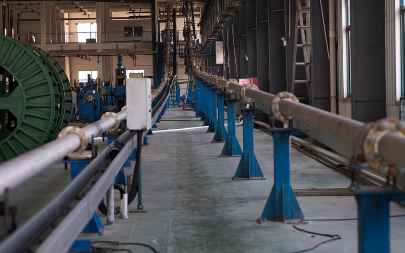
Quality Control
600/1000V PVC Insulated Cable to IEC 60502-1 Standard
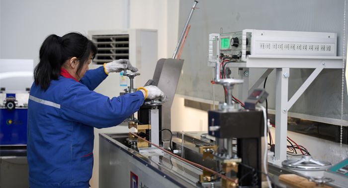
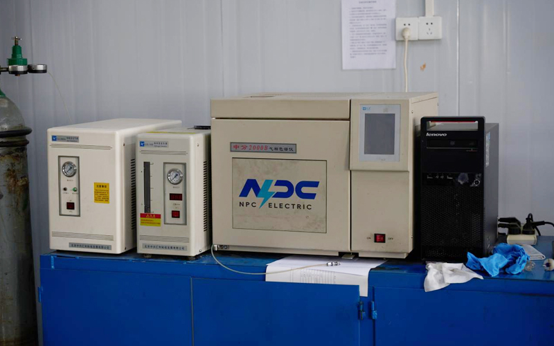
Raw Material Test
Raw Material Test is the first quality control stage for the 600/1000V PVC Insulated Low Voltage Power Cable. Copper or aluminum conductors are tested for electrical conductivity, tensile strength, and dimensional accuracy. PVC insulation compounds undergo thermal aging, elongation, and insulation resistance testing to confirm durability and safety. Any additional bedding or sheath materials are checked for mechanical strength and environmental resistance. Only raw materials that fully comply with technical specifications and applicable standards are approved for production, ensuring a stable foundation for cable manufacturing.
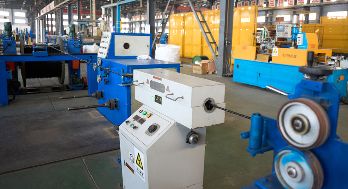
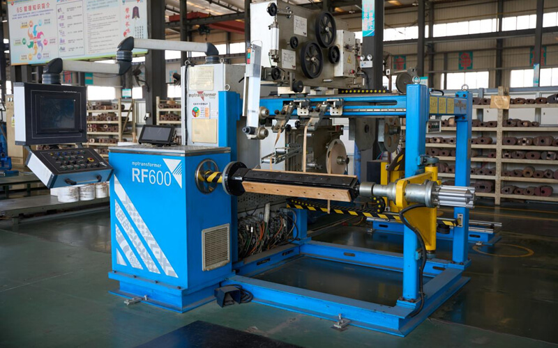
Process inspection
Process Inspection controls each manufacturing step of the 600/1000V PVC Insulated Low Voltage Power Cable. Conductor stranding is monitored for uniformity and correct lay length. PVC insulation extrusion is inspected for thickness consistency, concentricity, and surface quality. Continuous in-process electrical checks ensure insulation integrity throughout production. Dimensional inspections confirm compliance with design requirements. This systematic inspection process ensures consistent quality and reliable cable performance.
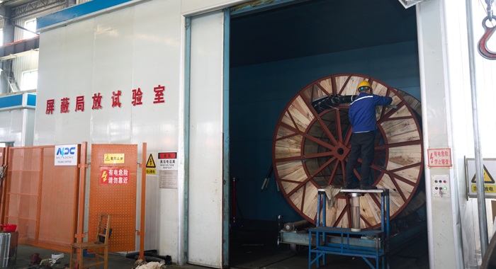
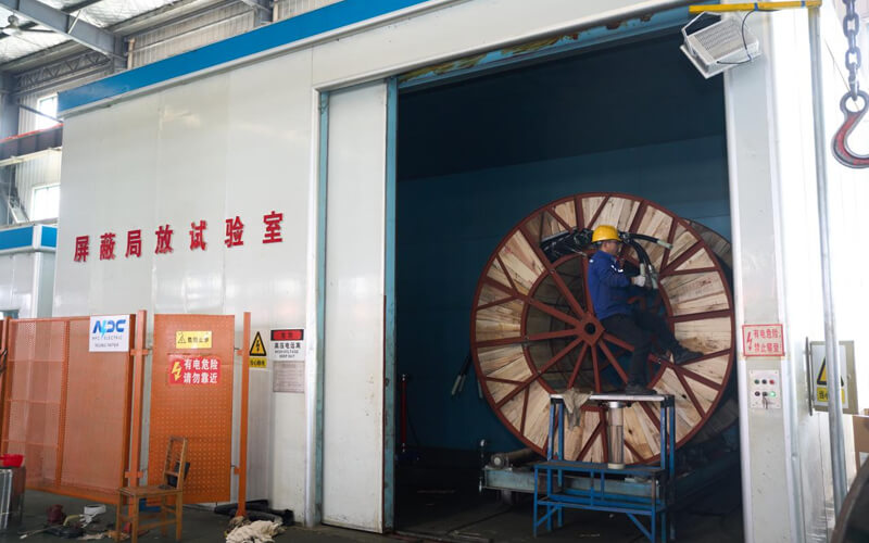
Finished Product
Finished Product Test verifies the final performance of the 600/1000V PVC Insulated Low Voltage Power Cable before delivery. Electrical tests include conductor resistance, insulation resistance, and voltage withstand testing. Mechanical tests assess tensile strength and insulation adhesion. Final visual inspection confirms correct construction, marking, and overall workmanship. Only cables that pass all tests are approved for shipment.
Application
Widely used in residential wiring, commercial buildings, industrial facilities, power distribution panels, and low voltage electrical networks requiring safe and reliable power transmission.


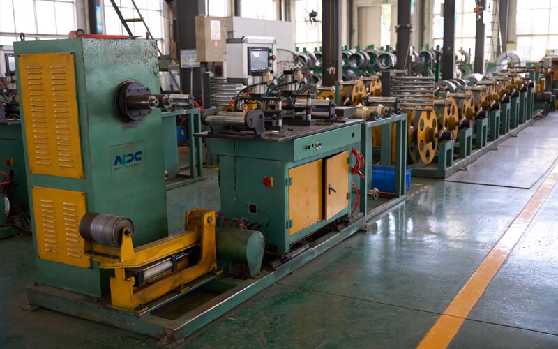
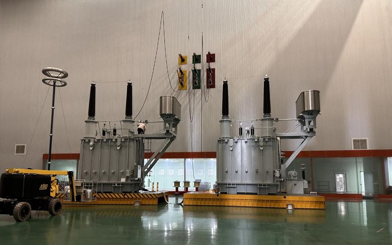
Technical Advantages
● 30+ years of manufacturing experience
● ISO and UL certified production
● Customized cable and transformer solutions
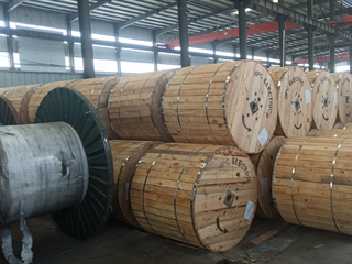
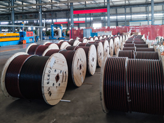
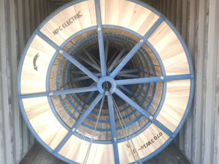
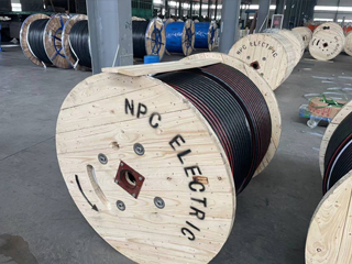
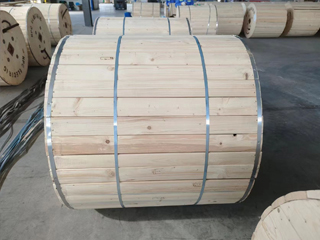
Product Packaging
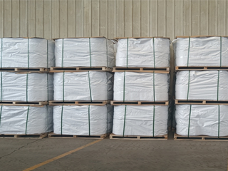
Wires and Cables packaging (1)
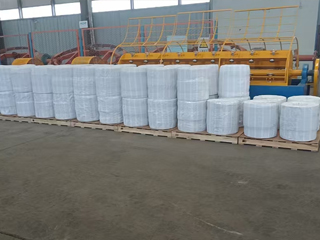
Wires and Cables packaging (2)
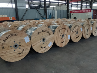
Wires and Cables packaging (3)
Wires and Cables packaging (4)
Wires and Cables packaging (5)
Wires and Cables packaging (6)
Wires and Cables packaging (7)
Wires and Cables packaging (8)
Related Products
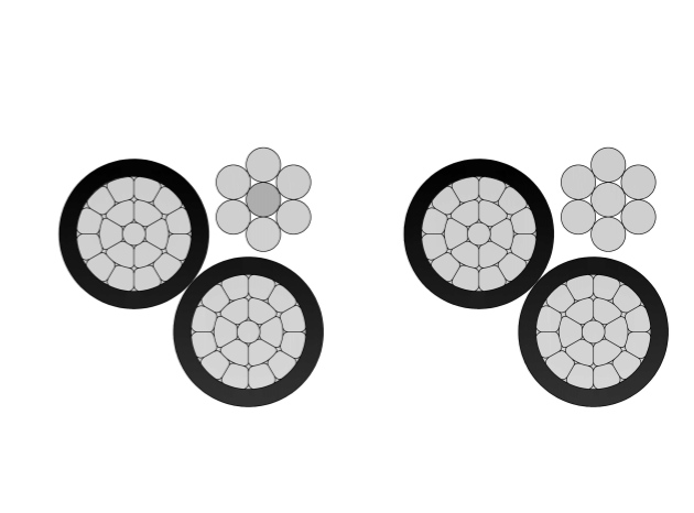
1/0 Purpura Aluminum Conductor Triplex Overhead Service Drop Cable
1/0 Purpura Triplex Aluminum Conductor Overhead Service Drop Cable is a durable and reliable aerial cable designed to deliver 600V power from utility lines to residential, commercial, or light industrial premises through a weatherhead service entrance. It consists of two insulated phase conductors and one bare neutral messenger, cabled together in a triplex configuration. The conductors are made of 1350-H19 aluminum, insulated with black cross-linked polyethylene (XLPE) for enhanced performance in extreme weather conditions, UV exposure, and mechanical stress.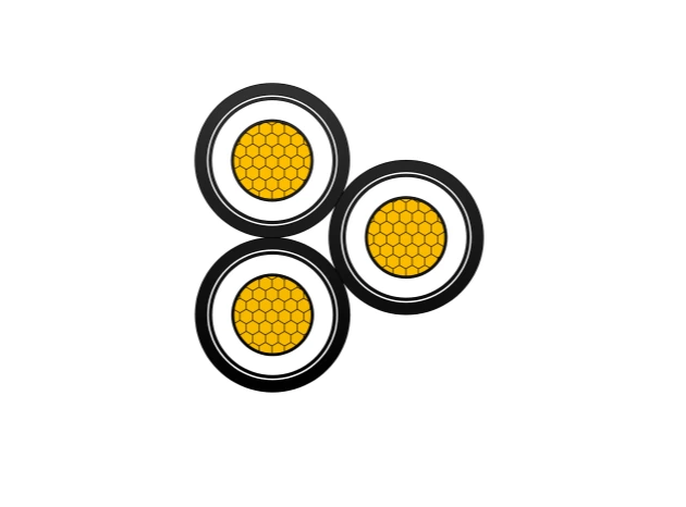
FR-N20XA8E-AR Triplex 12/20kV Cable Gen to NF C 33-226 - AL/XLPE/MDPE
The NF C 33-226 AL-XLPE-MDPE 12/20(24)kV Triplex Cable is a high-quality three-core medium voltage power cable designed for reliable three-phase energy transmission. It is constructed with Class 2 stranded aluminum conductors, cross-linked polyethylene (XLPE) insulation, and a medium-density polyethylene (MDPE) outer sheath, providing excellent electrical performance, thermal stability, and mechanical durability. Manufactured in accordance with NF C 33-226, IEC 60502-2, and EN 60228, this cable is ideal for industrial plants, municipal networks, and commercial power systems. It offers high resistance to water (AD7) and UV radiation (ISO 4892), and is halogen-free (IEC/EN 60754-1), ensuring safe and environmentally friendly operation. With a rated voltage of 12/20 (24)kV and a maximum conductor temperature of 90°C, this AL-XLPE-MDPE Triplex cable ensures efficient, safe, and long-term power transmission in medium-voltage distribution networks.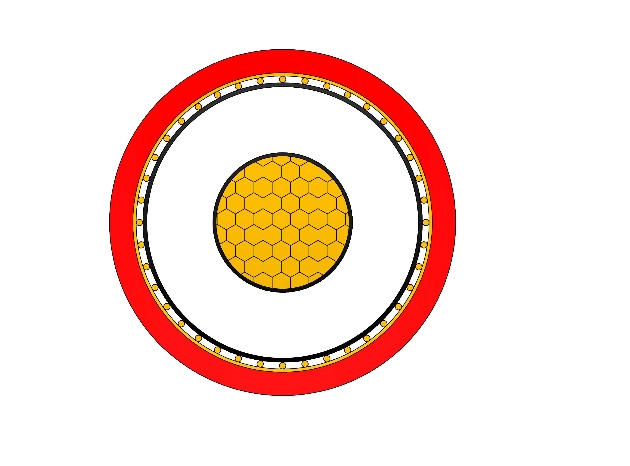
N2XSY Medium Voltage Power Cable(6/10kV, 12/20kV, 18/30kV)
N2XSY are medium voltage power cables with copper conductors and cross-linked polyethylene (XLPE) insulation, designed according to DIN VDE 0276-620 standards. Constructed with high-purity copper conductors, thermosetting XLPE insulation, metallic screen (copper tape or wires), and tough PVC outer sheath, it meets IEC 60502-2 requirements. The screen ensures electromagnetic compatibility and fault protection. Low tan delta, high breakdown strength, and excellent thermal endurance minimize losses and support overloads. PVC sheath provides solid mechanical and moisture protection for fixed installations. Optional longitudinal water-blocking improves performance in damp areas. Flame-retardant and easy to handle, the N2XSY Medium Voltage Power Cable is favored for power grids, manufacturing plants, commercial developments, and renewable energy sites demanding robust single-core medium voltage cabling with proven durability and cost efficiency in buried or tray installations worldwide.
3/0 Flustra Aluminum Conductor Triplex Overhead Service Drop Cable
The 3/0 Flustra Triplex Aluminum Overhead Service Drop Cable is a highly durable, weather-resistant cable designed for power distribution from utility poles to residential or light commercial buildings. This triplex cable includes two phase conductors and one bare neutral messenger, typically made of AAAC (All-Aluminum Alloy Conductor), providing both support and a current return path. With a voltage rating of 600V phase-to-phase and XLPE (Cross-Linked Polyethylene) insulation, this cable is built for high performance and reliability in aerial applications.
336.4 Nannynose Aluminum Conductor Triplex Overhead Service Drop Cable
The 336.4 Nannynose Triplex Aluminum Overhead Service Drop Cable is engineered for dependable power distribution from pole-mounted transformers to residential, commercial, and light industrial service entrances. This cable features two insulated aluminum phase conductors and a bare AAC (All-Aluminum Conductor) messenger that serves both as the neutral conductor and the mechanical support. The conductors are insulated with black cross-linked polyethylene (XLP), offering excellent UV protection, moisture resistance, and long-term outdoor durability.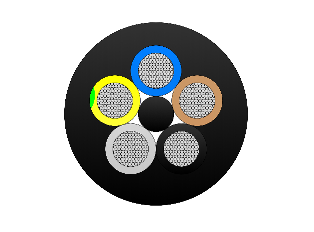
Type 210 Flexible Rubber Mining Cable
The Type 210 Flexible Rubber Mining Cable is a 1.1kV medium-voltage cable engineered for mining handheld drills and boring machines. It features flexible stranded tinned annealed copper conductors, EPR insulation, and a composite copper/polyester screen for improved electrical shielding. The heavy-duty PCP sheath offers oil resistance, abrasion protection, and flame retardancy, ensuring durability in harsh underground conditions. Compliant with AS/NZS 2802 and related standards, this cable delivers long-lasting performance in demanding environments requiring high flexibility and mechanical strength.FAQ From Customers
-
What are the advantages of power cables and overhead lines?(1) Reliable operation, because it is installed in a hidden place such as underground, it is less damaged by external forces, has less chance of failure, and the power supply is safe, and it will not cause harm to people; (2) The maintenance workload is small and frequent inspections are not required; (3) No need to erect towers; (4) Help improve power factor.
-
Which aspects should be considered when choosing the cross section of a power cable?(1) The long-term allowable working current of the cable; (2) Thermal stability once short circuited; (3) The voltage drop on the line cannot exceed the allowable working range.
-
What are the measures for cable fire prevention?(1) Use flame-retardant cables; (2) Use fireproof cable tray; (3) Use fireproof paint; (4) Fire partition walls and fire baffles are installed at cable tunnels, mezzanine exits, etc.; (5) Overhead cables should avoid oil pipelines and explosion-proof doors, otherwise local pipes or heat insulation and fire prevention measures should be taken.
-
What should be paid attention to during the transportation and handling of cables?(1) During transportation, loading and unloading, cables and cable reels should not be damaged. It is strictly forbidden to push the cable reels directly from the vehicle. Generally, cables should not be transported and stored flat. (2) Before transporting or rolling the cable reel, ensure that the cable reel is firm, the cable is wound tightly, the oil pipe between the oil-filled cable and the pressure oil tank should be fixed without damage, the pressure oil tank should be firm, and the pressure indication should meet the requirements.
-
What inspections should be carried out for the acceptance of cable lines?(1) The cable specifications should meet the regulations, the arrangement should be neat, no damage, and the signs should be complete, correct and clear; (2) The fixed bending radius of the cable, the related distance and the wiring of the metal sheath of the single-core power cable should meet the requirements; (3) The cable terminal and the middle head should not leak oil, and the installation should be firm. The oil pressure of the oil-filled cable and the meter setting should meet the requirements; (4) Good grounding; (5) The color of the cable terminal is correct, and the metal parts such as the bracket are completely painted; (6) There should be no debris in the cable trench, tunnel, and bridge, and the cover should be complete.
Welcome your inquiry
Honesty, Integrity, Frugality, Activeness and Passion