


600/1000V XLPE Insulated Low Voltage Power Cable to IEC 60502-1 Standard
The 600/1000V XLPE Insulated Low Voltage Power Cable manufactured to IEC 60502-1 is engineered to provide dependable power transmission in demanding electrical installations. High-purity conductors combined with XLPE insulation deliver excellent electrical stability, high current capacity, and resistance to thermal aging.
XLPE insulation allows higher operating temperatures and improved mechanical strength, ensuring long-term performance under continuous service conditions. Rated for 600/1000V systems, this cable supports safe and efficient power distribution in fixed installations. Compliance with IEC 60502-1 ensures the cable meets international standards for design, testing, and operational safety. Its robust construction makes it suitable for indoor, outdoor, and underground applications where durability and reliability are essential.
- Standard IEC 60502-1
Construction
Technical Specifications
Quality Control
Application
Construction
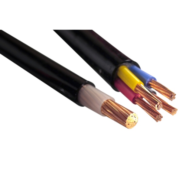
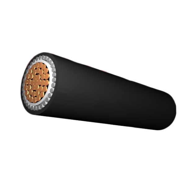
600/1000V XLPE Insulated Low Voltage Power Cable
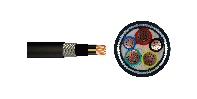
Conductor
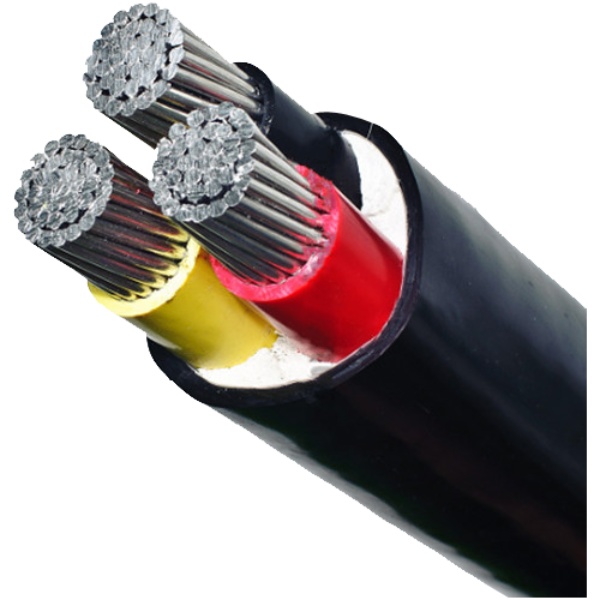
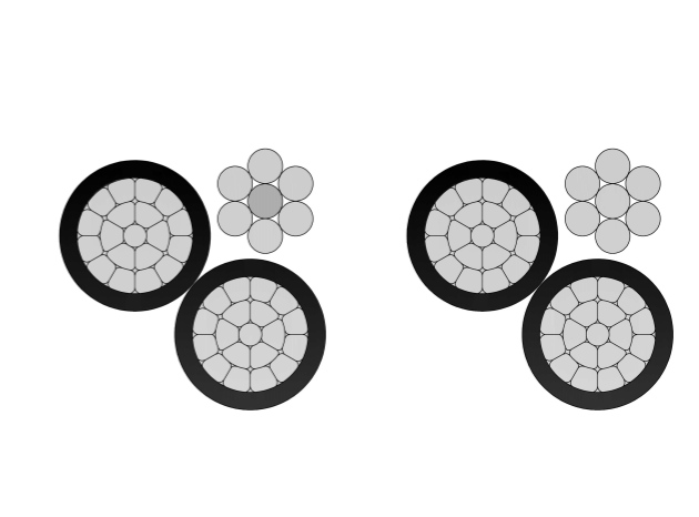
Copper or Aluminium conductor,round standed or Compacted,Class2 to IEC 60228,BS EN 60228.For smaller sizes,solid conductor, Class 1 as per IEC 60228, BS EN 60228 can also be supplied upon request.
Insulation
XLPE material and thickness shall be as per IEC 60502-1, rated for 90°C continuous operation.
Inner Covering
Inner sheath shall be of extruded PVC Type ST1/ST2 as per IEC 60502-1,Polyethylene type ST3/ST7, Halogen free compound ST8, Polychloroprene, chlorosulfonated polyethylene or similar polymers, type SE1 are also available on request.lapped is also applicable.
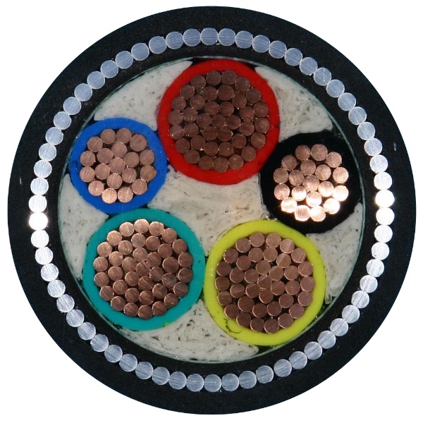
Armour
Aluminum/galvanized steel/steel wires applied helically over the Inner Covering as per IEC 60502-1, or double aluminum/steel tapes and copper/tinned copper wire can also be manufactured upon request.
Outer Sheath
Outer sheath shall be of extruded PVC Type ST1/ST2 as per IEC 60502-1,Polyethylene type ST3/ST7, Halogen free compound ST8, type SE1 are also available on request.
Fire Performance of Cable Sheaths
Cables can be supplied with special flame retardant PVC outer sheath to comply with the flame test requirements of IEC 60332-3-22, IEC 60332-3-23 and IEC 60332-3-24, Halogen Free material comply to IEC60754-1/2 and IEC 60684-2.
Color Code (1)
1 Core : Red or Black
2 Cores: Red, Black
3 Cores: Red, Yellow, Blue
4 Cores: Red, Yellow, Blue, Black
5 Cores: Red, Yellow, Blue, Black, Green
Above 5 Cores: Black Cores with White numerals
2 Cores: Red, Black
3 Cores: Red, Yellow, Blue
4 Cores: Red, Yellow, Blue, Black
5 Cores: Red, Yellow, Blue, Black, Green
Above 5 Cores: Black Cores with White numerals
Color Code (2)
1 Core : Brown or Blue
2 Cores : Brown, Blue
3 Cores : Brown, Black, Grey
4 Cores : Blue, Brown, Black, Grey
5 Cores : Green/Yellow, Blue, Brown, Black, Grey
Above 5 Cores: Black Cores with White numerals
Other colors can be manufactured upon request.
2 Cores : Brown, Blue
3 Cores : Brown, Black, Grey
4 Cores : Blue, Brown, Black, Grey
5 Cores : Green/Yellow, Blue, Brown, Black, Grey
Above 5 Cores: Black Cores with White numerals
Other colors can be manufactured upon request.
Technical Specifications
600/1000V XLPE Insulated Low Voltage Power Cable to IEC 60502-1 Standard
Single core(unarmoured)
Two cores(unarmoured)
Three cores(unarmoured)
Four cores(unarmoured)
Three cores+Earth(unarmoured)
Multi-cores(unarmoured)
Single core(Galvanized steel wire armoured)
Two cores(Galvanized steel wire armoured)
Three cores(Galvanized steel wire armoured)
Four cores(Galvanized steel wire armoured)
Three cores+ Earth(Galvanized steel wire armoured)
| Nominal Cross Section | Diameter of Conductor (Approx.) | Nominal Insulation Thickness | Nominal Sheath Thickness | Overall Diameter (Approx.) |
| mm² | mm | mm | mm | mm |
| 1 x 1.5 | 1.4 | 0.7 | 1.4 | 5.6 |
| 1 x 2.5 | 1.8 | 0.7 | 1.4 | 6 |
| 1 x 4 | 2.3 | 0.7 | 1.4 | 6.5 |
| 1 x 6 | 2.8 | 0.7 | 1.4 | 7 |
| 1 x 10 | 3.6 | 0.7 | 1.4 | 7.8 |
| 1 x 16 | 4.5 | 0.7 | 1.4 | 8.7 |
| 1 x 25 | 5.6 | 0.9 | 1.4 | 10.2 |
| 1 x 35 | 6.7 | 0.9 | 1.4 | 11.3 |
| 1 x 50 | 8 | 1 | 1.4 | 12.8 |
| 1 x 70 | 9.4 | 1.1 | 1.4 | 14.4 |
| 1 x 95 | 11 | 1.1 | 1.5 | 16.1 |
| 1 x 120 | 12.4 | 1.2 | 1.5 | 17.8 |
| 1 x 150 | 13.8 | 1.4 | 1.6 | 19.8 |
| 1 x 185 | 15.3 | 1.6 | 1.6 | 21.8 |
| 1 x 240 | 17.5 | 1.7 | 1.7 | 24.4 |
| 1 x 300 | 19.5 | 1.8 | 1.8 | 26.7 |
| 1 x 400 | 22.6 | 2 | 1.9 | 30.5 |
| 1 x 500 | 25.2 | 2.2 | 2 | 33.7 |
| 1 x 630 | 28.3 | 2.4 | 2.2 | 37.4 |
| 1 x 800 | 31.9 | 2.6 | 2.3 | 41.7 |
| 1 x 1000 | 35.7 | 2.8 | 2.4 | 46.2 |
| Nominal Cross Section | Diameter of Conductor (Approx.) | Nominal Insulation Thickness | Nominal Sheath Thickness | Overall Diameter (Approx.) |
| mm² | mm | mm | mm | mm |
| 2 x 1.5 | 1.4 | 0.7 | 1.8 | 9.2 |
| 2 x 2.5 | 1.8 | 0.7 | 1.8 | 10 |
| 2 x 4 | 2.3 | 0.7 | 1.8 | 11 |
| 2 x 6 | 2.8 | 0.7 | 1.8 | 12 |
| 2 x 10 | 3.6 | 0.7 | 1.8 | 13.6 |
| 2 x 16 | 4.5 | 0.7 | 1.8 | 15.4 |
| 2 x 25 | 5.6 | 0.9 | 1.8 | 18.4 |
| 2 x 35 | 6.7 | 0.9 | 1.8 | 20.6 |
| 2 x 50 | 8 | 1 | 1.8 | 23.6 |
| 2 x 70 | 9.4 | 1.1 | 1.8 | 26.8 |
| 2 x 95 | 11 | 1.1 | 1.9 | 30.2 |
| 2 x 120 | 12.4 | 1.2 | 2 | 33.7 |
| 2 x 150 | 13.8 | 1.4 | 2.2 | 37.5 |
| 2 x 185 | 15.3 | 1.6 | 2.3 | 41.6 |
| 2 x 240 | 17.5 | 1.7 | 2.5 | 46.7 |
| 2 x 300 | 19.5 | 1.8 | 2.6 | 51.4 |
| 2 x 400 | 22.6 | 2 | 2.9 | 58.9 |
| Nominal Cross Section | Diameter of Conductor (Approx.) | Nominal Insulation Thickness | Nominal Sheath Thickness | Overall Diameter (Approx.) |
| mm² | mm | mm | mm | mm |
| 3 x 1.5 | 1.4 | 0.7 | 1.8 | 9.6 |
| 3 x 2.5 | 1.8 | 0.7 | 1.8 | 10.5 |
| 3 x 4 | 2.3 | 0.7 | 1.8 | 11.6 |
| 3 x 6 | 2.8 | 0.7 | 1.8 | 12.6 |
| 3 x 10 | 3.6 | 0.7 | 1.8 | 14.4 |
| 3 x 16 | 4.5 | 0.7 | 1.8 | 16.3 |
| 3 x 25 | 5.6 | 0.9 | 1.8 | 19.5 |
| 3 x 35 | 6.7 | 0.9 | 1.8 | 21.9 |
| 3 x 50 | 8 | 1 | 1.8 | 25.1 |
| 3 x 70 | 9.4 | 1.1 | 1.9 | 28.7 |
| 3 x 95 | 11 | 1.1 | 2 | 32.4 |
| 3 x 120 | 12.4 | 1.2 | 2.1 | 36.1 |
| 3 x 150 | 13.8 | 1.4 | 2.3 | 40.3 |
| 3 x 185 | 15.3 | 1.6 | 2.4 | 44.6 |
| 3 x 240 | 17.5 | 1.7 | 2.6 | 50.2 |
| 3 x 300 | 19.5 | 1.8 | 2.7 | 55.2 |
| 3 x 400 | 22.6 | 2 | 3 | 63.3 |
| Nominal Cross Section | Diameter of Conductor (Approx.) | Nominal Insulation Thickness | Nominal Sheath Thickness | Overall Diameter (Approx.) |
| mm² | mm | mm | mm | mm |
| 4 x 1.5 | 1.4 | 0.7 | 1.8 | 10.4 |
| 4 x 2.5 | 1.8 | 0.7 | 1.8 | 11.3 |
| 4 x 4 | 2.3 | 0.7 | 1.8 | 12.5 |
| 4 x 6 | 2.8 | 0.7 | 1.8 | 13.7 |
| 4 x 10 | 3.6 | 0.7 | 1.8 | 15.7 |
| 4 x 16 | 4.5 | 0.7 | 1.8 | 17.8 |
| 4 x 25 | 5.6 | 0.9 | 1.8 | 21.5 |
| 4 x 35 | 6.7 | 0.9 | 1.8 | 24.1 |
| 4 x 50 | 8 | 1 | 1.8 | 27.8 |
| 4 x 70 | 9.4 | 1.1 | 2 | 32 |
| 4 x 95 | 11 | 1.1 | 2.1 | 36.1 |
| 4 x 120 | 12.4 | 1.2 | 2.3 | 40.2 |
| 4 x 150 | 13.8 | 1.4 | 2.4 | 44.9 |
| 4 x 185 | 15.3 | 1.6 | 2.6 | 49.8 |
| 4 x 240 | 17.5 | 1.7 | 2.8 | 56 |
| 4 x 300 | 19.5 | 1.8 | 3 | 61.7 |
| 4 x 400 | 22.6 | 2 | 3.2 | 70.7 |
| Nominal Cross Section | Diameter of Conductor (Approx.) | Nominal Insulation Thickness | Nominal Sheath Thickness | Overall Diameter (Approx.) | ||
| mm² | (3)mm | (1)mm | (3)mm | (1)mm | mm | mm |
| 3 x 16/10 | 4.5 | 3.6 | 0.7 | 0.7 | 1.8 | 17.5 |
| 3 x 25/16 | 5.6 | 4.5 | 0.9 | 0.7 | 1.8 | 21.2 |
| 3 x 35/16 | 6.7 | 4.5 | 0.9 | 0.7 | 1.8 | 23.8 |
| 3 x 50/25 | 8 | 5.6 | 1 | 0.9 | 1.8 | 27.5 |
| 3 x 70/35 | 9.4 | 6.7 | 1.1 | 0.9 | 2 | 31.7 |
| 3 x 95/50 | 11 | 8 | 1.1 | 1 | 2.1 | 35.8 |
| 3 x 120/70 | 12.4 | 9.4 | 1.2 | 1.1 | 2.3 | 39.9 |
| 3 x 150/70 | 13.8 | 9.4 | 1.4 | 1.1 | 2.4 | 44.6 |
| 3 x 185/95 | 15.3 | 11 | 1.6 | 1.1 | 2.6 | 49.5 |
| 3 x 240/120 | 17.5 | 12.4 | 1.7 | 1.2 | 2.8 | 55.7 |
| 3 x 300/150 | 19.5 | 13.8 | 1.8 | 1.4 | 3 | 61.4 |
| 3 x 400/185 | 22.6 | 15.3 | 2 | 1.6 | 3.2 | 70.4 |
| Nominal Cross Section | Diameter of Conductor (Approx.) | Nominal Insulation Thickness | Nominal Sheath Thickness | Overall Diameter (Approx.) |
| mm² | mm | mm | mm | mm |
| 5 x 1.5 | 1.4 | 0.7 | 1.8 | 11.2 |
| 7 x 1.5 | 1.4 | 0.7 | 1.8 | 12 |
| 10 x 1.5 | 1.4 | 0.7 | 1.8 | 14.8 |
| 12 x 1.5 | 1.4 | 0.7 | 1.8 | 15.2 |
| 14 x 1.5 | 1.4 | 0.7 | 1.8 | 16 |
| 19 x 1.5 | 1.4 | 0.7 | 1.8 | 17.6 |
| 21 x 1.5 | 1.4 | 0.7 | 1.8 | 18.4 |
| 24 x 1.5 | 1.4 | 0.7 | 1.8 | 20.4 |
| 30 x 1.5 | 1.4 | 0.7 | 1.8 | 21.6 |
| 40 x 1.5 | 1.4 | 0.7 | 1.8 | 26 |
| 48 x 1.5 | 1.4 | 0.7 | 1.8 | 26.4 |
| 61 x 1.5 | 1.4 | 0.7 | 1.9 | 29 |
| 5 x 2.5 | 1.8 | 0.7 | 1.8 | 12.2 |
| 7 x 2.5 | 1.8 | 0.7 | 1.8 | 13.2 |
| 10 x 2.5 | 1.8 | 0.7 | 1.8 | 16.4 |
| 12 x 2.5 | 1.8 | 0.7 | 1.8 | 16.9 |
| 14 x 2.5 | 1.8 | 0.7 | 1.8 | 17.7 |
| 19 x 2.5 | 1.8 | 0.7 | 1.8 | 19.6 |
| 21 x 2.5 | 1.8 | 0.7 | 1.8 | 20.6 |
| 24 x 2.5 | 1.8 | 0.7 | 1.8 | 22.8 |
| 30 x 2.5 | 1.8 | 0.7 | 1.8 | 24.1 |
| 40 x 2.5 | 1.8 | 0.7 | 1.9 | 29.4 |
| 48 x 2.5 | 1.8 | 0.7 | 1.9 | 29.9 |
| 61 x 2.5 | 1.8 | 0.7 | 2 | 32.8 |
| Nominal Cross Section |
Diameter of Conductor (Approx.) |
Nominal Insulation thickness |
Nominal Inner Covering thickness |
Nominal Alum Wire dia. |
Nominal Sheath thickness |
Overall Diameter (Approx.) |
| mm² | mm | mm | mm | mm | mm | mm |
| 1 x 4 | 2.3 | 0.7 | 1 | 0.8 | 1.8 | 10.9 |
| 1 x 6 | 2.8 | 0.7 | 1 | 0.8 | 1.8 | 11.4 |
| 1 x 10 | 3.6 | 0.7 | 1 | 0.8 | 1.8 | 12.2 |
| 1 x 16 | 4.5 | 0.7 | 1 | 0.8 | 1.8 | 13.1 |
| 1 x 25 | 5.6 | 0.9 | 1 | 0.8 | 1.8 | 14.6 |
| 1 x 35 | 6.7 | 0.9 | 1 | 1.25 | 1.8 | 16.6 |
| 1 x 50 | 8 | 1 | 1 | 1.25 | 1.8 | 18.1 |
| 1 x 70 | 9.4 | 1.1 | 1 | 1.25 | 1.8 | 19.7 |
| 1 x 95 | 11 | 1.1 | 1 | 1.6 | 1.8 | 22 |
| 1 x 120 | 12.4 | 1.2 | 1 | 1.6 | 1.8 | 23.6 |
| 1 x 150 | 13.8 | 1.4 | 1 | 1.6 | 1.8 | 25.4 |
| 1 x 185 | 15.3 | 1.6 | 1 | 1.6 | 1.8 | 27.4 |
| 1 x 240 | 17.5 | 1.7 | 1 | 1.6 | 1.9 | 29.9 |
| 1 x 300 | 19.5 | 1.8 | 1 | 2 | 2 | 33.1 |
| 1 x 400 | 22.6 | 2 | 1.2 | 2 | 2.2 | 37.3 |
| 1 x 500 | 25.2 | 2.2 | 1.2 | 2 | 2.3 | 40.5 |
| Nominal Cross Section |
Diameter of Conductor (Approx.) |
Nominal Insulation thickness |
Nominal Inner Covering thickness |
Nominal Alum Wire dia. |
Nominal Sheath thickness |
Overall Diameter (Approx.) |
| mm² | mm | mm | mm | mm | mm | mm |
| 2 x 1.5 | 1.4 | 0.7 | 1 | 0.8 | 1.8 | 12.8 |
| 2 x 2.5 | 1.8 | 0.7 | 1 | 0.8 | 1.8 | 13.6 |
| 2 x 4 | 2.3 | 0.7 | 1 | 0.8 | 1.8 | 14.6 |
| 2 x 6 | 2.8 | 0.7 | 1 | 1.25 | 1.8 | 16.5 |
| 2 x 10 | 3.6 | 0.7 | 1 | 1.25 | 1.8 | 18.1 |
| 2 x 16 | 4.5 | 0.7 | 1 | 1.25 | 1.8 | 19.9 |
| 2 x 25 | 5.6 | 0.9 | 1 | 1.6 | 1.8 | 23.6 |
| 2 x 35 | 6.7 | 0.9 | 1 | 1.6 | 1.8 | 25.8 |
| 2 x 50 | 8 | 1 | 1 | 1.6 | 1.9 | 29 |
| 2 x 70 | 9.4 | 1.1 | 1 | 2 | 2 | 33.2 |
| 2 x 95 | 11 | 1.1 | 1.2 | 2 | 2.1 | 37.1 |
| 2 x 120 | 12.4 | 1.2 | 1.2 | 2 | 2.3 | 40 |
| 2 x 150 | 13.8 | 1.4 | 1.2 | 2.5 | 2.4 | 45.4 |
| 2 x 185 | 15.3 | 1.6 | 1.4 | 2.5 | 2.6 | 49.9 |
| 2 x 240 | 17.5 | 1.7 | 1.4 | 2.5 | 2.7 | 55.1 |
| 2 x 300 | 19.5 | 1.8 | 1.6 | 2.5 | 2.9 | 60.2 |
| 2 x 400 | 22.6 | 2 | 1.6 | 2.5 | 3.1 | 67.7 |
| Nominal Cross Section |
Diameter of Conductor (Approx.) |
Nominal Insulation thickness |
Nominal Inner Covering thickness |
Nominal Alum Wire dia. |
Nominal Sheath thickness |
Overall Diameter (Approx.) |
| mm² | mm | mm | mm | mm | mm | mm |
| 3 x 1.5 | 1.4 | 0.7 | 1 | 0.8 | 1.8 | 13.2 |
| 3 x 2.5 | 1.8 | 0.7 | 1 | 0.8 | 1.8 | 14.1 |
| 3 x 4 | 2.3 | 0.7 | 1 | 0.8 | 1.8 | 15.2 |
| 3 x 6 | 2.8 | 0.7 | 1 | 1.25 | 1.8 | 17.1 |
| 3 x 10 | 3.6 | 0.7 | 1 | 1.25 | 1.8 | 18.9 |
| 3 x 16 | 4.5 | 0.7 | 1 | 1.25 | 1.8 | 20.8 |
| 3 x 25 | 5.6 | 0.9 | 1 | 1.6 | 1.8 | 24.7 |
| 3 x 35 | 6.7 | 0.9 | 1 | 1.6 | 1.8 | 27.2 |
| 3 x 50 | 8 | 1 | 1 | 1.6 | 1.9 | 30.6 |
| 3 x 70 | 9.4 | 1.1 | 1 | 2 | 2.1 | 35.2 |
| 3 x 95 | 11 | 1.1 | 1.2 | 2 | 2.2 | 39.3 |
| 3 x 120 | 12.4 | 1.2 | 1.2 | 2 | 2.3 | 43 |
| 3 x 150 | 13.8 | 1.4 | 1.4 | 2.5 | 2.5 | 48.6 |
| 3 x 185 | 15.3 | 1.6 | 1.4 | 2.5 | 2.7 | 53 |
| 3 x 240 | 17.5 | 1.7 | 1.4 | 2.5 | 2.8 | 58.5 |
| 3 x 300 | 19.5 | 1.8 | 1.6 | 2.5 | 3 | 64 |
| 3 x 400 | 22.6 | 2 | 1.6 | 3.15 | 3.3 | 73.5 |
| Nominal Cross Section |
Diameter of Conductor (Approx.) |
Nominal Insulation thickness |
Nominal Inner Covering thickness |
Nominal Alum Wire dia. |
Nominal Sheath thickness |
Overall Diameter (Approx.) |
| mm² | mm | mm | mm | mm | mm | mm |
| 4 x 1.5 | 1.4 | 0.7 | 1 | 0.8 | 1.8 | 14 |
| 4 x 2.5 | 1.8 | 0.7 | 1 | 0.8 | 1.8 | 14.9 |
| 4 x 4 | 2.3 | 0.7 | 1 | 1.25 | 1.8 | 17 |
| 4 x 6 | 2.8 | 0.7 | 1 | 1.25 | 1.8 | 18.2 |
| 4 x 10 | 3.6 | 0.7 | 1 | 1.25 | 1.8 | 20.2 |
| 4 x 16 | 4.5 | 0.7 | 1 | 1.6 | 1.8 | 23 |
| 4 x 25 | 5.6 | 0.9 | 1 | 1.6 | 1.8 | 26.7 |
| 4 x 35 | 6.7 | 0.9 | 1 | 1.6 | 1.9 | 29.5 |
| 4 x 50 | 8 | 1 | 1 | 2 | 2.1 | 34.2 |
| 4 x 70 | 9.4 | 1.1 | 1.2 | 2 | 2.2 | 38.8 |
| 4 x 95 | 11 | 1.1 | 1.2 | 2 | 2.3 | 42.9 |
| 4 x 120 | 12.4 | 1.2 | 1.4 | 2.5 | 2.5 | 48.6 |
| 4 x 150 | 13.8 | 1.4 | 1.4 | 2.5 | 2.7 | 53.2 |
| 4 x 185 | 15.3 | 1.6 | 1.4 | 2.5 | 2.8 | 58.1 |
| 4 x 240 | 17.5 | 1.7 | 1.6 | 2.5 | 3.1 | 64.8 |
| 4 x 300 | 19.5 | 1.8 | 1.6 | 2.5 | 3.2 | 70.4 |
| 4 x 400 | 22.6 | 2 | 1.8 | 3.15 | 3.6 | 81.3 |
| Nominal Cross Section |
Diameter of Conductor (Approx.) |
Nominal Insulation thickness |
Nominal Inner Covering thickness |
Nominal Steel Wire dia. |
Nominal Sheath thickness |
Overall Diameter (Approx.) |
||
| mm² | (3)mm | (1)mm | (3)mm | (1)mm | mm | mm | mm | mm |
| 3 x 16/10 | 4.5 | 3.6 | 0.7 | 0.7 | 1 | 1.6 | 1.8 | 22.7 |
| 3 x 25/16 | 5.6 | 4.5 | 0.9 | 0.7 | 1 | 1.6 | 1.8 | 26.5 |
| 3 x 35/16 | 6.7 | 4.5 | 0.9 | 0.7 | 1 | 1.6 | 1.9 | 29 |
| 3 x 50/25 | 8 | 5.6 | 1 | 0.9 | 1 | 1.6 | 2.1 | 33 |
| 3 x 70/35 | 9.4 | 6.7 | 1.1 | 0.9 | 1.2 | 2 | 2.2 | 38 |
| 3 x 95/50 | 11 | 8 | 1.1 | 1 | 1.2 | 2 | 2.3 | 42.4 |
| 3 x 120/70 | 12.4 | 9.4 | 1.2 | 1.1 | 1.2 | 2 | 2.5 | 48 |
| 3 x 150/70 | 13.8 | 9.4 | 1.4 | 1.1 | 1.4 | 2.5 | 2.7 | 52 |
| 3 x 185/95 | 15.3 | 11 | 1.6 | 1.1 | 1.4 | 2.5 | 2.8 | 57.2 |
| 3 x 240/120 | 17.5 | 12.4 | 1.7 | 1.2 | 1.6 | 2.5 | 3.1 | 64 |
| 3 x 300/150 | 19.5 | 13.8 | 1.8 | 1.4 | 1.6 | 2.5 | 3.2 | 69.8 |
| 3 x 400/185 | 22.6 | 15.3 | 2 | 1.6 | 1.6 | 3.15 | 3.6 | 78.6 |
Quality Control
600/1000V XLPE Insulated Low Voltage Power Cable to IEC 60502-1 Standard
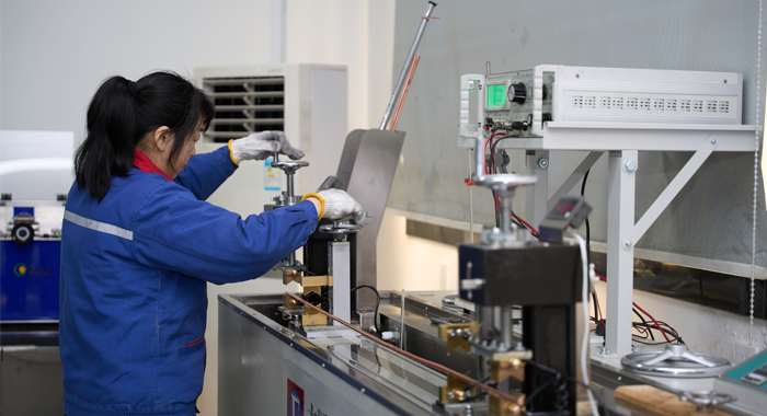
Raw Material Test
Raw Material Test is the first quality assurance step for the 600/1000V XLPE Insulated Low Voltage Power Cable to IEC 60502-1 Standard. Copper or aluminum conductors are tested for electrical conductivity, tensile strength, elongation, and dimensional accuracy. XLPE insulation compounds undergo strict testing for thermal aging, hot set performance, insulation resistance, and dielectric strength to ensure long-term reliability. Semi-conductive and bedding materials, where applicable, are inspected for compatibility and uniformity. All raw materials are verified against IEC 60502-1 technical requirements before being released to production, ensuring consistent cable quality and electrical safety.
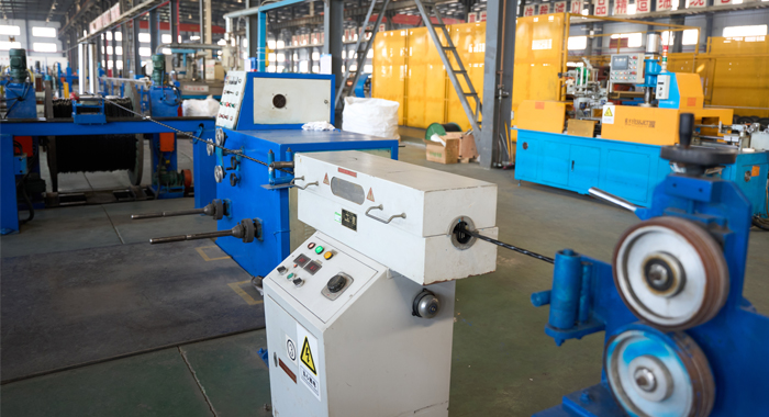
Process inspection
Process Inspection monitors each manufacturing stage of the 600/1000V XLPE Insulated Low Voltage Power Cable to IEC 60502-1 Standard. Conductor stranding is checked for correct lay length and uniformity. XLPE insulation extrusion is continuously inspected for thickness accuracy, concentricity, and surface smoothness. Cross-linking conditions are controlled to achieve optimal insulation properties. In-process electrical tests verify insulation integrity throughout production. Dimensional measurements and visual inspections are conducted at every step to ensure compliance with IEC 60502-1 standards and design specifications.
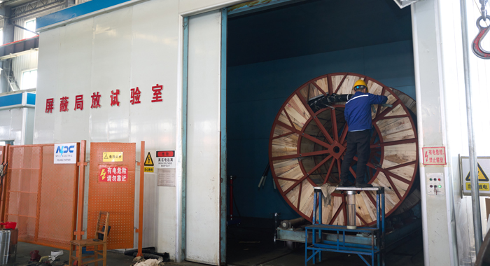
Finished Product
Finished Product Test confirms the final performance of the 600/1000V XLPE Insulated Low Voltage Power Cable to IEC 60502-1 Standard. Electrical testing includes conductor resistance measurement, insulation resistance testing, and AC voltage withstand testing as specified by IEC 60502-1. Mechanical tests assess insulation tensile strength and elongation after aging. Final inspections verify cable construction, marking accuracy, and overall workmanship. Only cables that fully comply with standard requirements are approved for shipment.
Application
Used in power distribution systems, industrial plants, commercial buildings, substations, and underground installations requiring IEC-compliant low-voltage XLPE insulated cables.


Technical Advantages
● 30+ years of manufacturing experience
● ISO and UL certified production
● Customized cable and transformer solutions


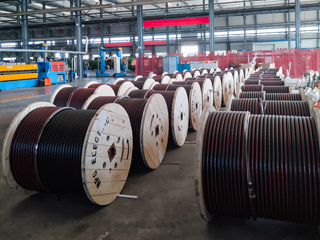
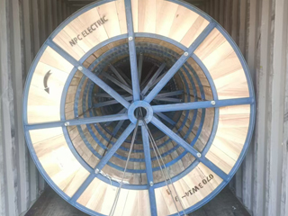
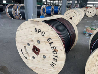
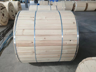
Product Packaging
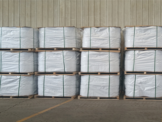
Wires and Cables packaging (1)
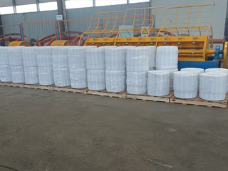
Wires and Cables packaging (2)
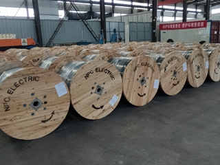
Wires and Cables packaging (3)
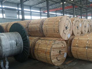
Wires and Cables packaging (4)
Wires and Cables packaging (5)
Wires and Cables packaging (6)
Wires and Cables packaging (7)
Wires and Cables packaging (8)
Related Products
Triplex Service Drop Cable
The Triplex Service Drop Cable is designed for overhead power distribution from utility lines to residential and commercial service entrances. It typically consists of two insulated phase conductors and one bare or insulated neutral messenger conductor, twisted together to provide mechanical support and electrical reliability. The phase conductors are insulated with weather-resistant materials such as XLPE or PE, offering excellent resistance to UV radiation, moisture, and environmental aging. Engineered for dependable performance, the Triplex Service Drop Cable ensures stable power delivery while minimizing line losses and installation complexity. Its lightweight yet robust construction allows for easy stringing across poles and buildings, while maintaining adequate tensile strength for long-span applications. Manufactured in accordance with applicable utility and industry standards, this cable is widely used in low-voltage overhead distribution networks where safety, durability, and long service life are essential.2Y-high-voltage-power-cable.webp)
2XS(FL)2Y MDPE High Voltage 36/60 (72.5)kV Power Cable
The 2XS(FL)2Y MDPE High Voltage Power Cable is a single-core aluminum conductor cable with XLPE insulation and an MDPE sheath, rated 36/60 (72.5) kV. Designed for high-voltage power transmission, it complies with IEC 60840 standards, delivering excellent electrical performance, robust mechanical protection, and outstanding water resistance for demanding applications. Its construction features a copper conductor, semi-conductive conductor screen, XLPE insulation, semi-conductive insulation screen, semi-conductive water swelling tape, copper wire metallic screen, longitudinal aluminum tape with PE copolymer coating, and a durable MDPE sheath. The water-blocking tape prevents water propagation inside the cable, ensuring reliable operation in power stations, industrial facilities, and distribution networks. This cable is suitable for distribution networks, connections to generation units, and industrial plants, with installation options including underground, underwater, outdoor, indoor, and cable ducts.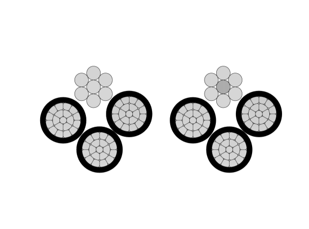
3/0 Suffolk Aluminum Conductor Quadruplex Overhead Service Drop Cable
The 3/0 Suffolk Quadruplex Service Drop Cable is a robust overhead cable for three-phase secondary power distribution with neutral. Featuring three 3/0 AWG aluminum phase conductors and one neutral messenger (7-strand) insulated with XLPE or PE and assembled in quadruplex configuration, it offers excellent mechanical strength and weather resistance. Compliant with ASTM B-230, B-231, ICEA S-76-474, and ANSI/ICEA standards, this cable supports 600V applications with superior UV, moisture, and abrasion protection. The self-supporting messenger reduces sag and simplifies installation over medium spans. The 3/0 Suffolk Quadruplex Service Drop Cable ensures low power losses, high current capacity, and long service life in harsh outdoor conditions. Lightweight and flexible, it is widely used for three-phase service drops in residential subdivisions, commercial buildings, and rural areas requiring safe, cost-effective aerial connections from utility poles to service entrances.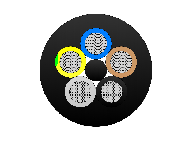
(N)TSCGEWOU 3.6/6kV, 6/10kV, 8.7/15kV and 12/20kV FO Cable
The (N)TSCGEWOU 3.6/6kV, 6/10kV, 8.7/15kV and 12/20kV FO Cable is a flexible, heavy-duty medium-voltage trailing/reeling cable with integrated fiber optic (FO) elements for combined power and high-speed data transmission in mining and tunneling. It features class 5 finely stranded tinned copper phase conductors for flexibility and corrosion resistance, semi-conductive screens, EPR insulation for superior dielectric strength and 90°C rating, copper braid screen for EMI protection and grounding, control conductors, monitoring conductor (ÜL), central or distributed multimode/single-mode fiber optic cores (protected in gel-filled tubes for water resistance and mechanical protection), and a tough rubber outer sheath resistant to oil, flame, abrasion, and mechanical stress. Compliant with DIN VDE 0250 and relevant IEC standards, it supports high tensile loads, fast reeling speeds, and tight bending radii while enabling real-time monitoring and communication. The (N)TSCGEWOU FO ensures safe, reliable MV power and data delivery to mobile equipment like shearers, tunnel boring machines, and smart conveyors in harsh underground environments.
1/0 Gammarus Aluminum Conductor Triplex Overhead Service Drop Cable
NPC Electric 1/0 Gammarus Triplex Service Drop Cable provides reliable overhead secondary distribution for residential applications. Consisting of two 1/0 AWG aluminum phase conductors and one neutral messenger (7-strand) insulated with cross-linked polyethylene (XLPE) and twisted in triplex form, it meets ASTM, ICEA, and international standards. The robust insulation resists sunlight, moisture, and mechanical damage for decades of outdoor service. Lightweight design simplifies installation with low sag and easy handling. The 1/0 Gammarus Triplex Service Drop Cable ensures minimal losses, high current capacity, and excellent weather performance up to 600V. Self-supporting messenger reduces pole loading. Flame-retardant options enhance safety. Commonly chosen for two-phase power delivery with neutral in subdivisions, rural homes, and temporary connections requiring safe, economical aerial bundled solutions with proven durability.2Y-high-voltage-power-cable.webp)
A2XS(FL)2Y HDPE High Voltage 64/110 (123) kV Power Cable
The A2XS(FL)2Y HDPE High Voltage 64/110 (123) kV Power Cable is a single-core aluminium conductor cable with XLPE insulation and HDPE sheath, designed in compliance with IEC 60840 standards. It offers excellent electrical performance, water resistance, and mechanical protection for high-voltage power transmission. Suitable for installation underground, underwater, outdoors, indoors, and in cable ducts, it ensures long-term reliability in power stations, industrial facilities, and distribution networks. The A2XS(FL)2Y HDPE is ideal for major HV transmission grids, underground/submarine lines, river crossings, offshore wind connections, and large-scale renewable energy projects where water ingress protection, efficiency, and long-term reliability are critical.FAQ From Customers
-
What are the advantages of power cables and overhead lines?(1) Reliable operation, because it is installed in a hidden place such as underground, it is less damaged by external forces, has less chance of failure, and the power supply is safe, and it will not cause harm to people; (2) The maintenance workload is small and frequent inspections are not required; (3) No need to erect towers; (4) Help improve power factor.
-
Which aspects should be considered when choosing the cross section of a power cable?(1) The long-term allowable working current of the cable; (2) Thermal stability once short circuited; (3) The voltage drop on the line cannot exceed the allowable working range.
-
What are the measures for cable fire prevention?(1) Use flame-retardant cables; (2) Use fireproof cable tray; (3) Use fireproof paint; (4) Fire partition walls and fire baffles are installed at cable tunnels, mezzanine exits, etc.; (5) Overhead cables should avoid oil pipelines and explosion-proof doors, otherwise local pipes or heat insulation and fire prevention measures should be taken.
-
What should be paid attention to during the transportation and handling of cables?(1) During transportation, loading and unloading, cables and cable reels should not be damaged. It is strictly forbidden to push the cable reels directly from the vehicle. Generally, cables should not be transported and stored flat. (2) Before transporting or rolling the cable reel, ensure that the cable reel is firm, the cable is wound tightly, the oil pipe between the oil-filled cable and the pressure oil tank should be fixed without damage, the pressure oil tank should be firm, and the pressure indication should meet the requirements.
-
What inspections should be carried out for the acceptance of cable lines?(1) The cable specifications should meet the regulations, the arrangement should be neat, no damage, and the signs should be complete, correct and clear; (2) The fixed bending radius of the cable, the related distance and the wiring of the metal sheath of the single-core power cable should meet the requirements; (3) The cable terminal and the middle head should not leak oil, and the installation should be firm. The oil pressure of the oil-filled cable and the meter setting should meet the requirements; (4) Good grounding; (5) The color of the cable terminal is correct, and the metal parts such as the bracket are completely painted; (6) There should be no debris in the cable trench, tunnel, and bridge, and the cover should be complete.
Welcome your inquiry
Honesty, Integrity, Frugality, Activeness and Passion