


Instrumentation Cables—PVC Insulated, Overall Screened, Unarmoured PVC Sheathed Cables (CU/PVC/OSCR/PVC)
Instrumentation Cables CU/PVC/OSCR/PVC are PVC Insulated, Overall Screened, Unarmoured PVC Sheathed Cables. They are multi-conductor cables that carry and transport low-voltage electrical signals. These low-voltage signals are used to control and monitor electrical power systems. Instrumentation cables have many different industrial applications that include broadcasting, equipment control, such as drilling and pumping in the oil and gas industry, and data transfer, which includes analog and digital signals. They are manufactured according to the BS EN 50288-7 and BS EN 50288-1 standards to ensure quality.
Depending on the application, instrumentation cables can be insulated with PVC or XLPE; the cables can be armoured or unarmoured. The sheathing materials can be of PVC, LSZH, or PE. The cables can have additional flame retardant or flame retardant properties, and they can be manufactured with special protections such as lead sheaths, or DRYLAM or AIRBAG technology.
- Standard BS EN 50288-7, IEC 60502-1 (General)
Construction
Technical Specifications
Quality Control
Application
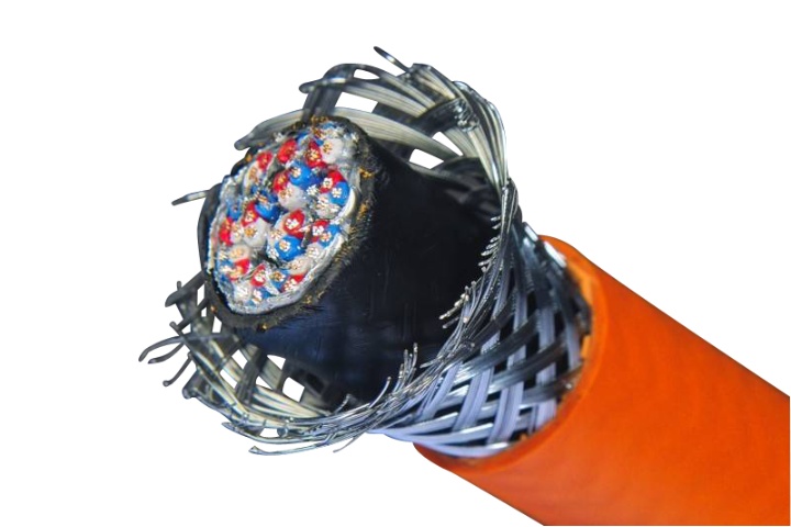
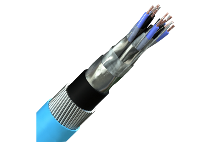
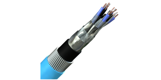
Construction
PVC Insulated, Overall Screened, Unarmoured PVC Sheathed Cables (CU/PVC/OSCR/PVC)
Conductor
Instrumentation cable shall have an annealed plain copper conductor or a tinned copper conductor. Depending upon cable application, conductor can be solid (Class-1), Stranded (Class-2), or flexible (Class-5) type as defined in BS EN / IEC 60228
Insulation
Instrumentation cable shall have PVC, XLPE, or HR-PVC insulation. Insulation material shall be selected based on the maximum operating temperature. PVC insulation is suitable for a continuous operating temperature of 70°C, whereas XLPE or HR-PVC is suitable for a continuous operating temperature of 90°C. Fire-rated / fire resistance instrumentation cables shall have Glass Mica Tape layer below insulation & shall have XLPE insulation.
Individual and Overall Screen
The screen is made of aluminum, mylar tape, + ATC drain wire. Aluminum mylar tape is made of aluminum with a thin layer of polyester. It helps in minimizing the crosstalk and prevents shorting.
Armour
Steel wire armour is applied to cables to shield against mechanical stresses and ensure that the core of the cable remains protected.
Inner and Outer Sheath
The sheath can be made of PVC, Polyethylene, or LSZH
Technical Specifications
Instrumentation Cables—PVC Insulated, Overall Screened, Unarmoured PVC Sheathed Cables (CU/PVC/OSCR/PVC)
Instrumentation Cables Main Specifications
Instrumentation Cables—PVC Insulated, Overall Screened, Unarmoured PVC Sheathed Cables (CU/PVC/OSCR/PVC)
| Conductor Size | Max. Conductor DC Resistance at 20°C for Plain Copper |
Max. Conductor DC Resistance at 20°C for Tinned Copper |
||
| Solid, Class - 1 & Stranded, Class - 2 |
Flexible, Class-5 | Solid, Class - 1 & Stranded, Class - 2 |
Flexible, Class-5 | |
| [mm2] | [Ω/km] | [Ω/km] | [Ω/km] | [Ω/km] |
| 0.50 | 36.72 | 39.78 | 37.434 | 40.902 |
| 0.75 | 24.99 | 26.52 | 25.296 | 27.234 |
| 1.00 | 18.462 | 19.89 | 18.564 | 20.4 |
| 1.50 | 12.342 | 13.566 | 12.444 | 13.974 |
| 2.50 | 7.5582 | 8.1396 | 7.7112 | 8.3742 |
| Conductor Size | Insulation Thickness | |||
| 90V | 300V | 500V | 1000V | |
| [mm2] | [mm] | [mm] | [mm] | [mm] |
| 0.50 | 0.20 | 0.26 | 0.44 | 0.70 |
| 0.75 | 0.20 | 0.26 | 0.44 | 0.70 |
| 1.00 | 0.26 | 0.26 | 0.44 | 0.70 |
| 1.50 | 0.30 | 0.35 | 0.44 | 0.70 |
| 2.50 | - | - | 0.53 | 0.70 |
| Conductor Size | Mutual Capacitance | Max. Continuous Operating Temperature | Inductance to Resistance Ratio (L/R) |
||
| XLPE | PVC | XLPE or HR - PVC | PVC | ||
| [mm2] | [nF/km] | [nF/km] | [°C] | [°C] | [μH/Ω] |
| 0.50 | 150 | 250 | 90 | 70 | < 25 |
| 0.75 | 150 | 250 | 90 | 70 | < 25 |
| 1.00 | 150 | 250 | 90 | 70 | < 25 |
| 1.50 | 150 | 250 | 90 | 70 | < 40 |
| 2.50 | 150 | 250 | 90 | 70 | < 60 |
| Number of Pair | Cable OD | Cable Weight | Drum Length | ||||||||
| 0.5mm² | 0.75mm² | 1.0mm² | 1.5mm² | 2.5mm² | 0.5mm² | 0.75mm² | 1.0mm² | 1.5mm² | 2.5mm² | ||
| [Nos] | [mm] | [mm] | [mm] | [mm] | [mm] | [kg/km] | [kg/km] | [kg/km] | [kg/km] | [kg/km] | [m] |
| 1 | 6.5 | 7.0 | 7.5 | 8.0 | 9.0 | 50 | 60 | 70 | 80 | 110 | 1000 |
| 2 | 9.0 | 10.0 | 10.5 | 11.5 | 14.0 | 85 | 105 | 120 | 145 | 205 | 1000 |
| 5 | 11.5 | 13.0 | 13.5 | 15.0 | 17.5 | 155 | 195 | 230 | 285 | 415 | 1000 |
| 10 | 16.5 | 17.5 | 19.0 | 21.0 | 25.5 | 280 | 350 | 415 | 535 | 800 | 1000 |
| 20 | 21.0 | 23.0 | 24.5 | 27.5 | 33.0 | 495 | 635 | 765 | 990 | 1490 | 1000 |
| 30 | 24.5 | 27.0 | 29.0 | 32.5 | 705 | 910 | 1110 | 1445 | 500 | ||
| Number of Triad | Cable OD | Cable Weight | Drum Length | ||||||||
| 0.5mm² | 0.75mm² | 1.0mm² | 1.5mm² | 2.5mm² | 0.5mm² | 0.75mm² | 1.0mm² | 1.5mm² | 2.5mm² | ||
| [Nos] | [mm] | [mm] | [mm] | [mm] | [mm] | [kg/km] | [kg/km] | [kg/km] | [kg/km] | [kg/km] | [m] |
| 1 | 7 | 7.5 | 7.5 | 8.5 | 10 | 60 | 75 | 85 | 100 | 145 | 1000 |
| 2 | 10 | 11 | 11.5 | 13 | 15 | 110 | 135 | 155 | 195 | 275 | 1000 |
| 5 | 13 | 14 | 15 | 16.5 | 20 | 210 | 260 | 310 | 400 | 590 | 1000 |
| 10 | 18 | 20 | 21 | 23.5 | 28.5 | 375 | 485 | 585 | 750 | 1135 | 1000 |
| 20 | 23.5 | 26 | 27.5 | 31 | 690 | 895 | 1085 | 1405 | 500 | ||
| 30 | 28 | 30.5 | 33 | 990 | 1290 | 1585 | 500 | ||||
| Number of Quad | Cable OD | Cable Weight | Drum Length | ||||||||
| 0.5mm² | 0.75mm² | 1.0mm² | 1.5mm² | 2.5mm² | 0.5mm² | 0.75mm² | 1.0mm² | 1.5mm² | 2.5mm² | ||
| [Nos] | [mm] | [mm] | [mm] | [mm] | [mm] | [kg/km] | [kg/km] | [kg/km] | [kg/km] | [kg/km] | [m] |
| 1 | 7.5 | 8 | 8.5 | 9 | 10.5 | 75 | 85 | 100 | 125 | 180 | 1000 |
| 2 | 12.5 | 13.5 | 14.5 | 16 | 19.5 | 140 | 175 | 205 | 260 | 375 | 1000 |
| 5 | 16 | 17.5 | 19 | 21 | 25 | 275 | 345 | 410 | 530 | 795 | 1000 |
| 10 | 23 | 25 | 27 | 30 | 36 | 510 | 645 | 785 | 1015 | 1525 | 1000 |
| 20 | 29.5 | 32.5 | 35 | 930 | 1205 | 1455 | 500 | ||||
| 30 | 35.5 | 1345 | 500 | ||||||||
Note: Cable OD and Cable weight are subject to change based on the latest manufacturing practice.
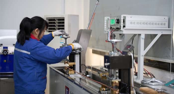
Quality Control
Instrumentation Cables—PVC Insulated, Overall Screened, Unarmoured PVC Sheathed Cables (CU/PVC/OSCR/PVC)
Raw Material Test
For the Instrumentation Cables—PVC Insulated, Overall Screened, Unarmoured PVC Sheathed Cables (CU/PVC/OSCR/PVC), raw material testing ensures compliance with BS EN 50288-7. Step 1: Verify copper conductor purity using spectrometry to confirm 99.99% conductivity per IEC 60228. Step 2: Test PVC insulation for tensile strength (≥12.5 N/mm²) and elongation (≥150%) via universal testing machines. Step 3: Evaluate screening tape (aluminum/polyester) for thickness and adhesion through micrometer measurements and peel tests. Step 4: Assess PVC sheath flame retardancy with oxygen index analysis (>27%). Step 5: Conduct chemical resistance immersion on PVC in oils, acids, and water for 168 hours. Batch sampling (10%) and traceability documentation reject substandard materials, guaranteeing EMI protection and durability in the final product.
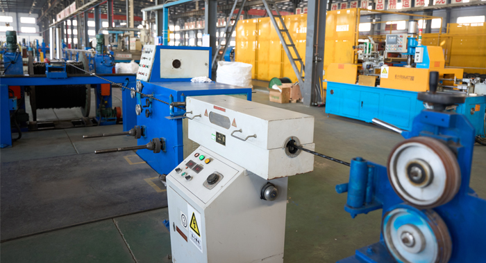
Process inspection
During the manufacturing of the Instrumentation Cables—PVC Insulated, Overall Screened, Unarmoured PVC Sheathed Cables (CU/PVC/OSCR/PVC), process inspection maintains BS EN 50288-1 standards. Step 1: Monitor conductor stranding for uniform twists using automated gauges every 100 meters. Step 2: Scan insulation extrusion thickness (nominal 0.7mm) with lasers, flagging deviations over 5%. Step 3: Inspect pair twisting and core assembly visually and mechanically. Step 4: Apply the overall screen and verify coverage uniformity via ultrasonic probes. Step 5: Conduct in-line capacitance and continuity tests to ensure low interference. Step 6: Check sheath application adhesion through peel strength evaluations (≥10 N/cm). Step 7: Sample every shift for dimensional accuracy and screen integrity. Step 8: Log data digitally for ISO 9001 audits. This multi-step oversight minimizes defects, ensuring reliable signal transmission and compliance.
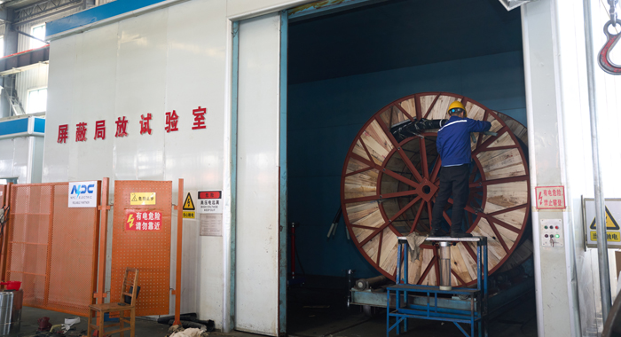
Finished Product
The finished Instrumentation Cables—PVC Insulated, Overall Screened, Unarmoured PVC Sheathed Cables (CU/PVC/OSCR/PVC) undergo comprehensive testing per BS EN 50288-7. Step 1: Perform voltage withstand at 1.5 kV for 1 minute to verify insulation. Step 2: Measure insulation resistance (>100 MΩ/km) using megohmmeters. Step 3: Test conductor resistance per IEC 60228 standards. Step 4: Evaluate screening effectiveness via transfer impedance tests (<1 Ω/m at 1 MHz). Step 5: Conduct flame retardancy (IEC 60332-1) and bending (10x diameter). Step 6: Assess capacitance unbalance and crosstalk attenuation. Step 7: Cycle temperatures (-15°C to 70°C) for 48 hours. Step 8: Final visual and electrical inspections ensure no defects. Calibrated tools and 100% critical testing confirm performance for industrial use.
Application
The Instrumentation Cables—PVC Insulated, Overall Screened, Unarmoured PVC Sheathed Cables (CU/PVC/OSCR/PVC) excel in process plants, petrochemical facilities, power stations, and automation systems. They provide EMI-protected signal transmission in ducts, trays, and indoor/outdoor setups, ideal for control circuits and monitoring equipment.


Technical Advantages
● 30+ years of manufacturing experience
● ISO and UL certified production
● Customized cable and transformer solutions


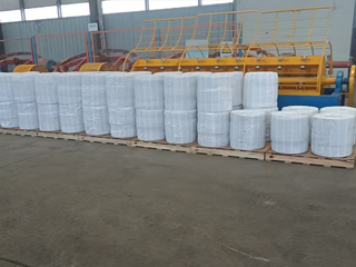
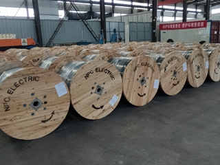
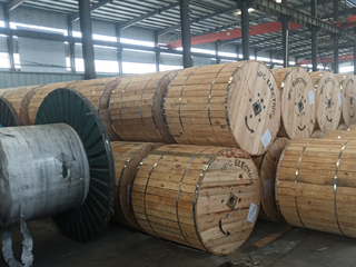
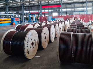
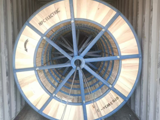
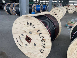
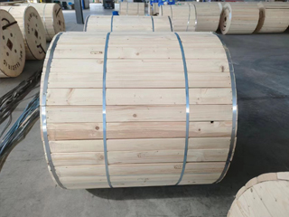
Product Packaging
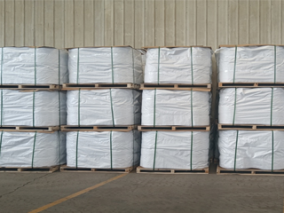
Wires and Cables packaging (1)
Wires and Cables packaging (2)
Wires and Cables packaging (3)
Wires and Cables packaging (4)
Wires and Cables packaging (5)
Wires and Cables packaging (6)
Wires and Cables packaging (7)
Wires and Cables packaging (8)
Related Products
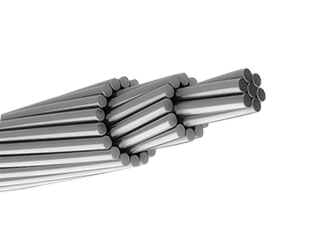
954 MCM CARDINAL ACSR Conductor Cable
The ACSR CAA 954 MCM 54/7F CARDINAL is a high-capacity, heavy-duty Aluminium Conductor Steel Reinforced (ACSR) cable engineered for the reliable transmission of electrical power over long-span overhead lines. It features 54 hard-drawn 1350-H19 aluminium strands concentrically laid around 7 galvanized steel strands, offering an optimized balance between excellent electrical conductivity and mechanical strength. Manufactured to meet the requirements of ASTM B232, the CARDINAL configuration is a trusted industry standard, widely adopted in high-voltage transmission systems. The galvanized steel core, available in Class A or B coatings, provides superior corrosion resistance and structural support, making this conductor ideal for outdoor environments exposed to wind, ice, and mechanical loading. The 54/7F strand design ensures increased current-carrying capacity and lower resistance, making it suitable for use in critical infrastructure and utility-grade transmission networks. Its cost-effective design makes it popular for utility upgrades and rural electrification, ensuring reliable power delivery with minimal maintenance in overhead transmission and distribution systems worldwide.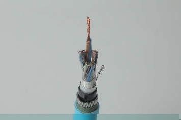
Instrumentation Cables—XLPE Insulated,Individual &Overall Screened,Unarmoured PVC Sheathed Cables(CU/XLPE/IOSCR/PVC)
Instrumentation Cables are multi-conductor cables that carry and transport low-voltage electrical signals. These low-voltage signals are used to control and monitor electrical power systems. Instrumentation cables have many different industrial applications that include broadcasting, equipment control, such as drilling and pumping in the oil and gas industry, and data transfer, which includes analog and digital signals. They are manufactured according to the BS EN 50288-7 and BS EN 50288-1 standards to ensure quality. Depending on the application, instrumentation cables can be insulated with PVC or XLPE; the cables can be armoured or unarmoured. The sheathing materials can be of PVC, LSZH, or PE. The cables can have additional flame retardant or flame retardant properties, and they can be manufactured with special protections such as lead sheaths, or DRYLAM or AIRBAG technology.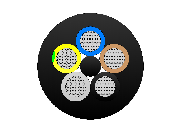
YSLTOE-J 300/500V Cable
The YSLTOE-J 300/500V Cable is a flexible low-voltage control cable featuring tinned copper conductors and a halogen-free, oil-resistant PUR outer sheath. It is engineered for gravity-feed collector baskets in modern high-speed container cranes, ensuring reliable performance under moderate mechanical stress and in oily industrial environments. Manufactured to DIN VDE 0281 and related standards, it offers excellent tensile strength, abrasion resistance, and flexibility. For proper installation, the cable must be mounted torsion-free in a counter-clockwise direction, with a basket diameter exceeding 30× the cable’s outer diameter to prevent damage.
397.5 MCM IBIS ACSR Conductor Cable
The ACSR CAA 397.5 MCM 26/7F IBIS conductor is a high-strength aluminium conductor steel reinforced (ACSR) cable, engineered for use in overhead transmission and distribution systems where both mechanical durability and electrical performance are critical. Manufactured in accordance with ASTM B232, this conductor is constructed with 26 strands of hard-drawn 1350-H19 aluminium helically laid over 7 galvanized steel strands, offering an optimal balance between conductivity, corrosion resistance, and tensile strength. The steel core, galvanized to Class A or B standards, provides structural support and resistance to environmental corrosion, while the outer aluminium layers ensure efficient current-carrying capacity. This concentric-lay stranded design makes the IBIS conductor a reliable and widely used solution in medium- and high-voltage power networks, particularly for long-span overhead lines.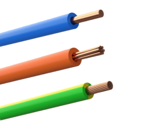
H07V-U H07V-R H07V-K
H07V-K cable is used for the internal wiring of electric motors and transformers as well as other electrical appliances and lighting applications. It can be used in and at electronic appliances for measuring, regulating and controlling. The cables are also ideal for laying in pipes, surface wiring and conduit installations. Specifications according to HD 516 apply for respective specific applications. H07V-U cable is intended for the installation to inside of apparatus as well as for the protective laying to the lightings, in dry rooms, in production facilities, switch and distributor boards, in tubes, under and surface mounting of plasters. H07V-R cable is preferably for installation indoors, in cable ducts, and in industrial plants or switching stations, under ground installation. It can be used in switchboards and distributor boards or where a thicker strand of multi-wire is required. Found in electronic and electrical equipment and switch gear cabinets designed for export to a European country and for MRO replacement of European-made equipment wire.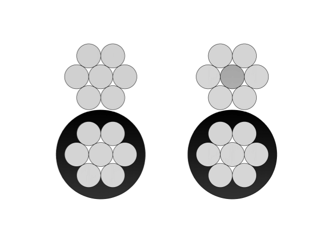
NS75/NS90 Duplex Unjacketed Overhead Neutral Supported Cable
Our NS75/NS90 Duplex Unjacketed Overhead Neutral Supported Cable provides economical self-supporting overhead distribution. Consisting of an XLPE-insulated aluminum phase conductor (75 mm² or 95 mm²) supported by a bare ACSR or AAAC neutral messenger without an overall jacket, it meets AS/NZS 3560 and utility requirements. The design reduces material costs while delivering high tracking resistance and mechanical strength for spans up to 100m. Excellent UV and moisture performance ensures longevity in exposed conditions. The NS75/NS90 Duplex Unjacketed Overhead Neutral Supported Cable offers low installation effort, minimal sag, and reliable power delivery for 600/1000V networks. Widely favored in Australia and New Zealand for residential, commercial, and rural service drops requiring lightweight, neutral-supported overhead cables with proven compliance and durability in diverse climates.FAQ From Customers
-
What are the advantages of power cables and overhead lines?(1) Reliable operation, because it is installed in a hidden place such as underground, it is less damaged by external forces, has less chance of failure, and the power supply is safe, and it will not cause harm to people; (2) The maintenance workload is small and frequent inspections are not required; (3) No need to erect towers; (4) Help improve power factor.
-
Which aspects should be considered when choosing the cross section of a power cable?(1) The long-term allowable working current of the cable; (2) Thermal stability once short circuited; (3) The voltage drop on the line cannot exceed the allowable working range.
-
What are the measures for cable fire prevention?(1) Use flame-retardant cables; (2) Use fireproof cable tray; (3) Use fireproof paint; (4) Fire partition walls and fire baffles are installed at cable tunnels, mezzanine exits, etc.; (5) Overhead cables should avoid oil pipelines and explosion-proof doors, otherwise local pipes or heat insulation and fire prevention measures should be taken.
-
What should be paid attention to during the transportation and handling of cables?(1) During transportation, loading and unloading, cables and cable reels should not be damaged. It is strictly forbidden to push the cable reels directly from the vehicle. Generally, cables should not be transported and stored flat. (2) Before transporting or rolling the cable reel, ensure that the cable reel is firm, the cable is wound tightly, the oil pipe between the oil-filled cable and the pressure oil tank should be fixed without damage, the pressure oil tank should be firm, and the pressure indication should meet the requirements.
-
What inspections should be carried out for the acceptance of cable lines?(1) The cable specifications should meet the regulations, the arrangement should be neat, no damage, and the signs should be complete, correct and clear; (2) The fixed bending radius of the cable, the related distance and the wiring of the metal sheath of the single-core power cable should meet the requirements; (3) The cable terminal and the middle head should not leak oil, and the installation should be firm. The oil pressure of the oil-filled cable and the meter setting should meet the requirements; (4) Good grounding; (5) The color of the cable terminal is correct, and the metal parts such as the bracket are completely painted; (6) There should be no debris in the cable trench, tunnel, and bridge, and the cover should be complete.
Welcome your inquiry
Honesty, Integrity, Frugality, Activeness and Passion