Why We Need Tap Changers on the Transformer
2025-05-16
In modern electrical power systems, maintaining voltage levels within an acceptable range is essential for both system stability and equipment longevity. As power flows fluctuate throughout a distribution network, the voltage at various points changes due to load variations, line impedance, and other dynamic conditions. One of the most effective solutions for this challenge lies within the transformer: tap changers.
The Role of Tap Changers in Voltage Regulation
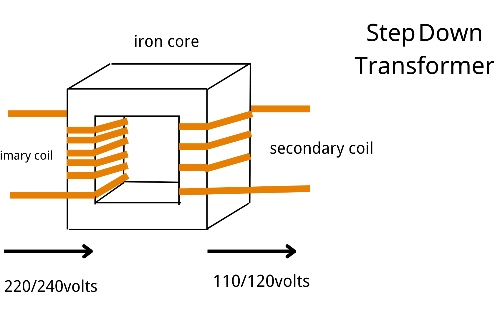
Transformers operate on the principle of electromagnetic induction, where the turns ratio between the primary and secondary windings determines the voltage transformation. However, the demand on the distribution network is rarely static, which means that the voltage delivered to end-users can vary. To ensure a stable secondary voltage, we need a way to modify the transformer's effective turns ratio without replacing or rewiring the unit.
This is where tap changers become critical. By adjusting the number of active turns on the voltage winding, tap changers allow utilities to maintain voltage levels within strict limits, even as load conditions change.
Tap Changer Types: On-Load vs. De-Energized
There are two main categories of transformer tap changers: De-energized Tap Changers (DETCs) and On-Load Tap Changers (OLTCs).
- De-energized Tap Changers (DETCs) are designed for manual or motor-operated adjustment only when the transformer is offline. These are typically found on smaller voltage transformers or power transformers that do not require frequent adjustment. While cost-effective, DETCs do not allow real-time voltage regulation.
- On-Load Tap Changers (OLTCs), by contrast, are engineered to adjust the taps while the transformer remains in service. They are commonly used in larger power transformers and high-demand environments where voltage needs to be actively regulated in real time.
Table 1: Tap Changer Comparison (DETC vs OLTC)
|
Feature |
DETC (De-energized Tap Changer) |
OLTC (On-Load Tap Changer) |
|
Voltage adjustment while live? |
No (requires shutdown) |
Yes (under load) |
|
Adjustment frequency |
Low |
High (dynamic regulation) |
|
Typical application |
Distribution transformers |
Transmission, power transformers |
|
Complexity |
Simple |
Complex (selector + diverter) |
|
Cost |
Lower |
Higher |
|
Maintenance requirements |
Low |
High |
|
Tap location |
High-voltage winding |
High-voltage winding |
How OLTCs Work: Selector and Diverter Switches
An OLTC functions through a combination of mechanical and electrical components, most notably the selector switch and the diverter switch. The selector switch determines which tap the transformer is connected to, while the diverter switch handles the transition between taps under load without interrupting the circuit.
Here’s a simplified sequence:
- The selector switch selects the next tap.
- The diverter switch uses switch contacts and a bridging mechanism to momentarily connect both the old and new taps, allowing a seamless transfer.
- Once the load is fully shifted, the previous tap is disconnected.
This precise control allows the load tap changer to incrementally vary the transformer's turns ratio, thereby altering the output voltage in small, controlled steps. In high-voltage transmission systems, this function is indispensable.
Voltage Taps and Transformer Windings
A transformer typically has voltage taps located on the high-voltage winding. This is because adjusting the turns on the primary side (where the voltage is higher) requires fewer current-handling capabilities compared to the low-voltage side. The taps are spaced out in steps, commonly ±10% of the nominal voltage in increments of 1.25% or 2.5%.
Each voltage tap corresponds to a different number of winding turns, allowing the transformer to compensate for voltage sags or surges.
Table 2: Voltage Tap Position and Corresponding Voltage Shift
|
Tap Position |
Effective Turns (%) |
Output Voltage Change |
Application Example |
|
Tap -4 |
90% |
-10% |
Light load, high input voltage |
|
Tap -2 |
95% |
-5% |
Voltage slightly above nominal |
|
Tap 0 (neutral) |
100% |
0% |
Rated voltage |
|
Tap +2 |
105% |
+5% |
Medium load compensation |
|
Tap +4 |
110% |
+10% |
Heavy load or distant end load |
Note: In real applications, tap steps are typically 1.25% or 2.5%, depending on the transformer design.
Applications and Benefits in the Distribution Network
In a real-world distribution network, tap changers help maintain optimal voltage conditions across various load scenarios—morning peaks, evening dips, or sudden industrial loads. Without this adaptive control, utilities would face more frequent voltage complaints, equipment malfunctions, and overall inefficiencies.
Tap changers also:
- Improve power quality and reduce losses.
- Extend the life of connected equipment.
- Minimize the need for manual intervention.
- Support integration of renewable energy sources, where voltage variability is common.
Challenges and Considerations
While tap changers offer numerous advantages, they do introduce mechanical complexity and require regular maintenance. OLTCs, in particular, involve oil-insulated compartments and moving parts that must be serviced periodically to avoid failure.
Moreover, improper tap settings—especially in DETCs—can lead to suboptimal performance or even equipment damage. It is essential for system designers and operators to understand the transformer tap configuration during commissioning and load planning.
Related Articles
Related Products
(N)TSCGECEWOU 8.7/15kV and 12/20kV ATB Cable
The (N)TSCGECEWOU 8.7/15kV and 12/20kV ATB cable is a flexible high-voltage power cable designed for tunnel boring machines and other heavy-duty mobile equipment operating under high mechanical stress. Built to VDE standards, it features Class 5 tinned copper conductors, EPR insulation, halogen-free flame-retardant sheath, and a polyester anti-torsion braid for exceptional performance in reeling and trailing applications. With abrasion resistance, oil resistance, and outdoor durability, this cable ensures reliable high-voltage power transmission in demanding mining and tunneling environments.
Coil End Lead Type 4 BS 6195 Cable
The Coil End Lead Type 4 BS 6195 Cable is a premium, highly flexible high-temperature lead wire engineered for demanding coil and transformer applications. It features fine-stranded tinned copper conductors for superior conductivity and corrosion resistance, high-purity silicone rubber insulation providing excellent dielectric strength, exceptional heat resistance (continuous 180°C, short-term 220°C), and outstanding flexibility even in cold conditions. Compliant with BS 6195 Type 4 standard, it offers flame retardancy, ozone resistance, and long-term thermal stability without cracking or hardening. The cable is lightweight, easy to strip, and suitable for tight bending radii in coil winding, motor connections, and transformer lead-outs. The Coil End Lead Type 4 BS 6195 Cable ensures reliable performance in high-heat environments, reducing downtime and enhancing safety in electrical equipment manufacturing and repair.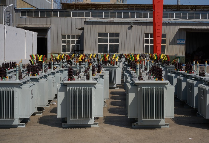
30kVA Oil Immersed Transformer
30kVA Oil Immersed Transformer, produced by a reputable manufacturer and supplier in China, represents the pinnacle of electrical engineering excellence. These transformers are engineered with precision and cutting-edge technology to provide robust, efficient, and long-lasting power solutions.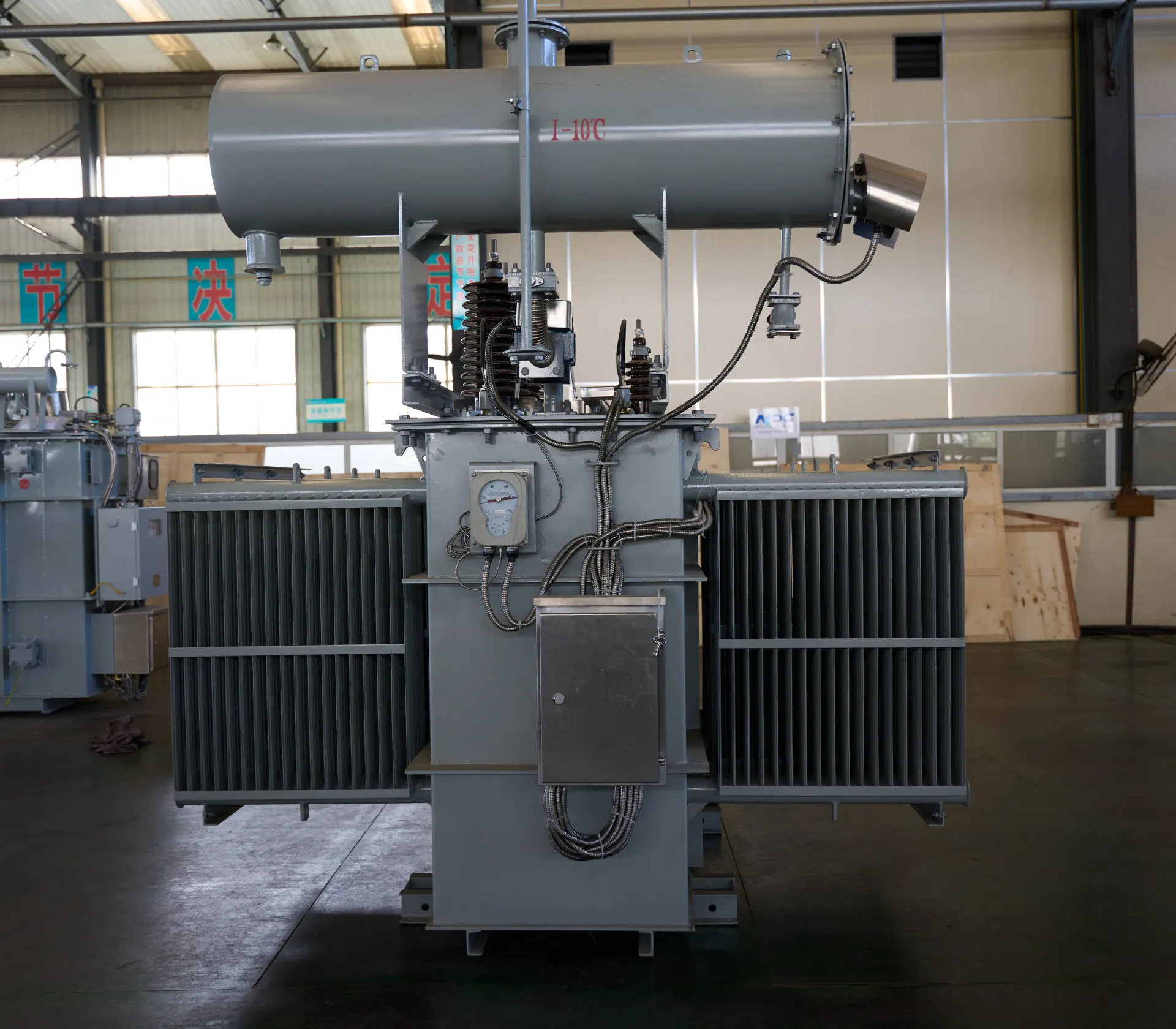
11kV to 0.8kV 1250 kVA Solar Power Transformer - Copper Wound High Efficiency PV Transformer
The 1250 kVA Solar Power Step-Up Transformer is a high-performance, inverter-duty solution specifically engineered for utility-scale photovoltaic (PV) installations. Designed to interface directly with 800V central or string inverters, this unit efficiently elevates voltage to 11kV for medium-voltage distribution. Unlike standard distribution transformers, our 1250 kVA model features 100% high-purity oxygen-free copper windings, offering superior thermal conductivity and lower losses. The core is constructed from laser-scribed, grain-oriented silicon steel to minimize eddy current losses, ensuring maximum energy harvest even during low-irradiance periods. With advanced harmonic mitigation technology, it withstands the high-frequency switching stresses typical of modern solar power conversion.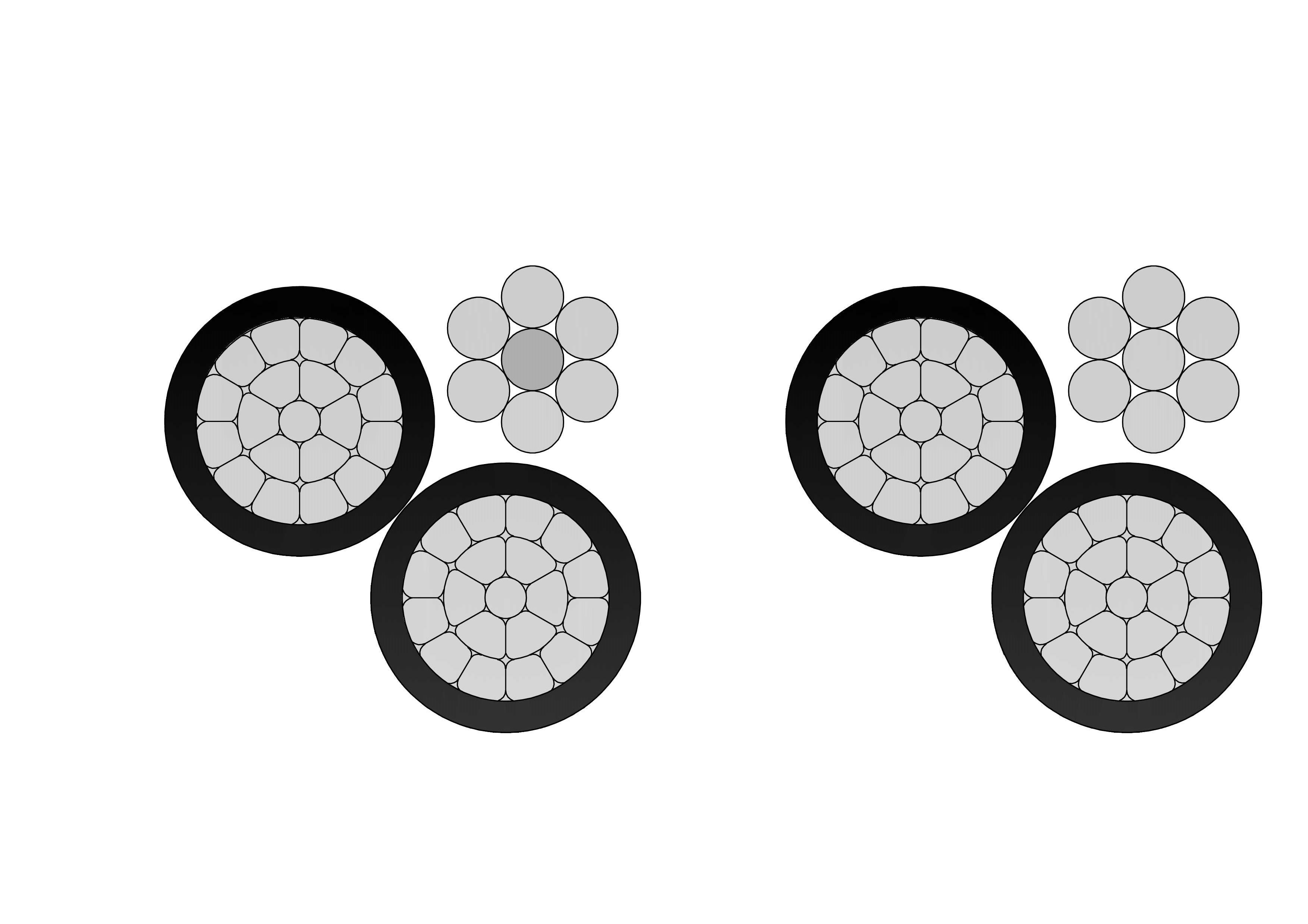
1/0 Ranella Aluminum Conductor Triplex Overhead Service Drop Cable
1/0 Ranella Triplex Service Drop Cable is a reliable overhead cable for secondary power distribution to residential service entrances. Featuring two 1/0 AWG aluminum phase conductors and one neutral messenger (7-strand) insulated with XLPE or PE and assembled in triplex configuration, it provides excellent mechanical strength and weather resistance. Compliant with ASTM B-230, B-231, ICEA S-76-474, and ANSI/ICEA standards, this cable supports 600V applications with high UV, moisture, and abrasion protection. The self-supporting messenger reduces sag and simplifies installation over medium spans. The 1/0 Ranella Triplex Service Drop Cable ensures low power losses, high current capacity, and long service life in harsh outdoor conditions. Lightweight and flexible, it is widely used for two-phase service drops with neutral in urban, suburban, and rural areas requiring safe, cost-effective aerial connections from utility poles to homes.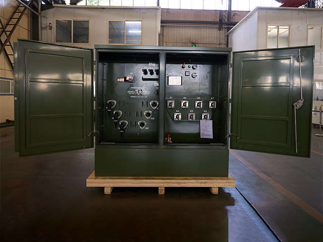
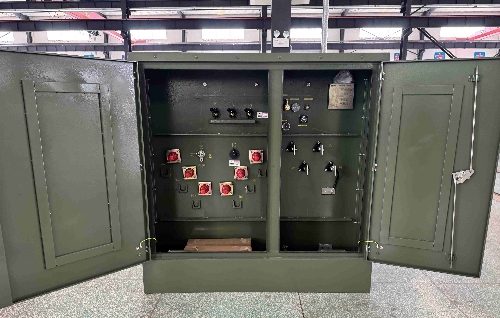
250kVA Three Phase Pad Mounted Transformer
The 250kVA Three Phase Pad Mounted Transformer is a compact, liquid-immersed, self-cooled (ONAN) distribution transformer optimized for efficient, underground power delivery in residential, light commercial, and small industrial applications. Fully compliant with IEEE C57.12.34, ANSI C57.12.00, DOE 2016 efficiency standards, and UL-listed, this compartmental-type unit features dead-front 200A high-voltage bushing wells (loadbreak inserts), radial or loop feed options, and a sealed tank using non-PCB mineral oil or FR3 natural ester fluid for improved fire safety and environmental performance.
80kVA Oil Immersed Transformer
NPC ELECTRIC 80kva Oil Immersed Transformer boasts a robust design that incorporates high-quality materials and advanced manufacturing techniques. The transformer's core is made from premium cold-rolled silicon steel sheets, ensuring low loss and high efficiency. The oil-immersed design of the NPC ELECTRIC 80kVA transformer provides effective cooling and insulation, ensuring that the transformer operates within safe temperature limits and maintains optimal performance. The oil also acts as a dielectric medium, enhancing the transformer's electrical properties and protecting it from environmental factors.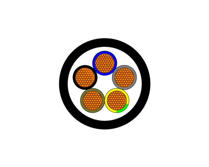
N2XY IEC 60502-1 XLPE PVC 0.6/1kV Cable
N2XY cable is a low-voltage power cable consisting of copper conductors, XLPE (cross-linked polyethylene) insulation, and a PVC (polyvinyl chloride) sheath, manufactured in accordance with IEC 60502-1 standards. Designed for 0.6/1kV fixed installations, it offers excellent electrical performance, mechanical strength, and thermal resistance, making it ideal for power transmission in industrial, commercial, and infrastructure projects.
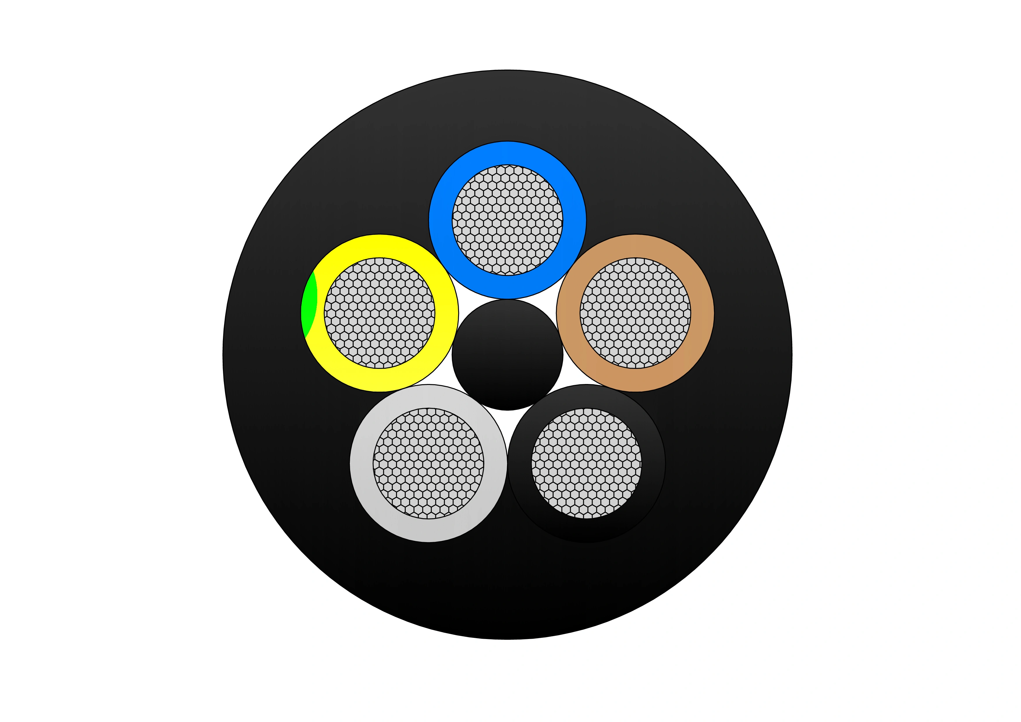
(N)TSKCGEWOU 3.6/6kV, 6/10kV, 8.7/15kV and 12/20kV Cable
The (N)TSKCGEWOU 3.6/6kV, 6/10kV, 8.7/15kV, 12/20kV Cable is a rugged flexible medium-voltage cable optimized for dynamic mining and tunneling applications. It includes tinned class 5 copper phase conductors, semi-conductive screens, EPR insulation for outstanding dielectric and thermal properties (90°C rating), copper braid screen for shielding, control conductors, monitoring conductor (ÜL), and a heavy-duty rubber sheath resistant to oils, flames, abrasion, and mechanical damage. Compliant with DIN VDE 0250, it provides high flexibility, torsional strength, and EMC protection across voltage levels for extreme conditions. The (N)TSKCGEWOU ensures dependable MV energy delivery to mobile machinery such as excavators, draglines, shearers, and tunnel boring equipment in opencast and underground mining, enhancing safety, reducing voltage drop, and supporting long service life.
Quadruplex Service Drop Cable
NPC Electric Quadruplex Service Drop Cable offers efficient overhead three-phase service with neutral support. Comprising three-phase conductors (aluminum) insulated with XLPE or PE and helically twisted around a strong neutral messenger (ACSR, AAC, or covered aluminum), it meets ASTM, ICEA, and international standards. The messenger provides full self-support, allowing longer spans and reduced infrastructure costs. Premium insulation resists sunlight, moisture, and mechanical abrasion for decades of outdoor service. Lightweight and flexible, it simplifies installation with low sag. The Quadruplex Service Drop Cable ensures minimal losses, high mechanical endurance, and excellent weather performance up to 600V. Flame-retardant options enhance safety. Perfect for reliable power delivery in urban developments, commercial areas, street lighting, and temporary sites requiring safe, cost-effective aerial bundled solutions.
XAI Armoured Medium Voltage Power Cable(6/10kV, 12/20kV, 18/30kV)
NPC Electric XAI Armoured Medium Voltage Power Cable (6/10kV, 12/20kV, 18/30kV) delivers protected, high-performance medium voltage transmission. Constructed with copper or aluminium conductors, thermosetting XLPE insulation, metallic screen, bedding, galvanised steel wire armour (SWA), and tough outer sheath, it meets IEC 60502-2 requirements. The SWA layer offers outstanding resistance to mechanical damage, enabling direct burial without conduits. Low transmission losses, high current rating, and excellent overload tolerance ensure optimal efficiency. Optional LSZH sheath and water-blocking for added safety and reliability. Flame-retardant and environmentally robust, the XAI Armoured Medium Voltage Power Cable is widely selected for power grids, manufacturing plants, wind/solar farms, and infrastructure demanding reliable, maintenance-free medium voltage cabling with enhanced mechanical safeguarding in challenging terrains or high-impact zones worldwide.
15kVA Single Phase Pad Mounted transformer
The 15 kVA single phase pad mounted transformer operates safely, reliably, and efficiently and can be installed indoors and outdoors. This type of transformer has a low operating cost, is environmentally friendly, easy to install, and has a low purchase cost, so it is widely used in residential, commercial, and other public.
4000kVA Oil Immersed Transformer
4000kVA Oil Immersed Transformer is designed for medium and large-scale power distribution systems that require high reliability, strong overload capacity, and long-term stable operation. The transformer adopts a fully sealed oil-immersed structure, effectively preventing moisture ingress and oil oxidation, thereby extending service life and reducing maintenance frequency. The transformer features excellent thermal performance and robust insulation strength, ensuring stable operation under continuous load or fluctuating grid conditions. Advanced oil circulation and cooling structure enhance heat dissipation, while precise manufacturing processes guarantee low noise and high mechanical strength.
50kVA Single Phase Pad Mounted transformer
NPC ELECTRIC 50 kVA pad mounted transformer meets/exceeds DOE 2016 efficiency ratings with UL/cUL listed. Design and production with ANSI/IEEE, CSA standards.NPC ELECTRIC Transformer's 50 kVA single-phase pad-mounted transformer is extensively employed in the North American market. With their wealth of project experience,NPC ELECTRIC Transformer caters to a diverse clientele, including builders, public utility departments, and transformer distributors and retailers.
33kV Cast Resin Dry Type Transformer 1000kVA–5000kVA Three Phase
The 33kV Cast Resin Dry Type Transformer 1000kVA–5000kVA Three Phase is a high-capacity, oil-free power solution engineered for demanding indoor medium- and high-voltage distribution networks. This robust three-phase cast resin transformer utilizes premium low-loss grain-oriented silicon steel cores and high-conductivity copper windings (aluminum optional) fully encapsulated in high-grade epoxy resin under vacuum pressure, delivering exceptional energy efficiency (typically 98.5–99.5%), significantly reduced no-load and load losses, and superior partial discharge performance (<10pC). Fully compliant with IEC 60076-11, IEEE/ANSI, and relevant energy efficiency standards, this transformer steps down 33kV primary (with ±2×2.5% to ±10% off-circuit taps standard) to secondary voltages such as 0.4kV, 0.69kV, 6.6kV, or 11kV (Dyn11 vector group typical).Welcome your inquiry
Honesty, Integrity, Frugality, Activeness and Passion