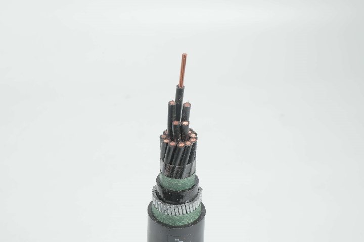
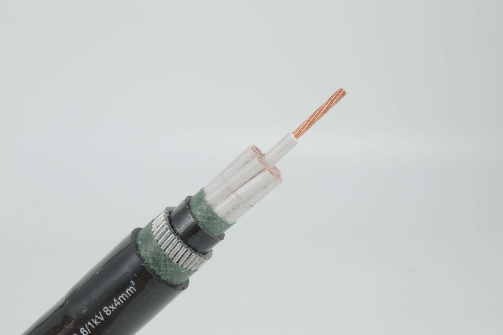
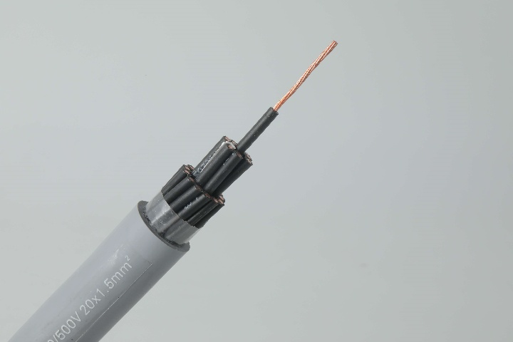


Control Cable 0.6/1 kV CVV-SWA to IEC 60502 Standard (2-16 core)
NPC Electric Control Cable 0.6/1 kV CVV-SWA to IEC 60502 Standard (2-16 core) is built for maximum protection in demanding control applications. It features concentric stranded copper conductors for excellent conductivity and flexibility, insulated with high-grade black PVC and identified by white numbers. A copper tape shield minimizes electromagnetic interference, while the steel wire armour (SWA) provides superior mechanical protection against impacts, rodents, and crushing. Dual PVC sheaths enhance flame retardancy and resistance to moisture and chemicals. Rated for voltages up to 1 kV, it operates reliably from -15°C to 70°C. Compliant with IEC 60502, this cable is suited for supervisory circuits, power stations, and installations in ducts, trays, underground, or direct burial. With 2 to 16 cores, it handles complex control setups, ensuring signal integrity and reducing downtime. Ideal for industrial environments requiring robust defence, the CVV-SWA delivers long-term durability, cost efficiency, and safety through advanced engineering and quality materials.
- Standard IEC 60502-1, IEC 60228
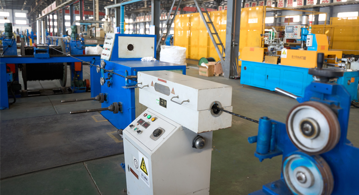
Construction
Technical Specifications
Quality Control
Application
Construction
Control Cable 0.6/1 kV CVV-SWA to IEC 60502 Standard
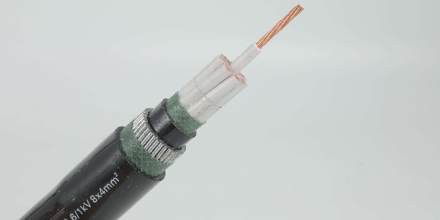
Conductor
Concentric Stranded annealed copper wire
Insulation
PVC Black color
Identification
Printed White number on the surface of Black insulation
Filler
Suitable filler
Binding tape
Suitable tape
Inner sheath
PVC Black color
Outer Sheath
PVC Black color
Armour
Galvanized steel wire
Binding tape
Suitable tape
Technical Specifications
Control Cable 0.6/1 kV CVV-SWA to IEC 60502 Standard (2-16 core)
2 Cores, 3 Cores and 4 Cores
5 Cores, 6 Cores and 7 Cores
8 Cores, 9 Cores and 10 Cores
11 Cores, 12 Cores and 13 Cores
14 Cores, 15 Cores and 16 Cores
| No. of core |
Nominal cross sectional area |
No.& dia. of wires |
Thickness of inner sheath |
Diameter of steel wire armour |
Thickness of outer sheath |
Overall diameter (Approx.) |
Minimum insulation resistance (at70ºC) |
Cable weight (Approx.) |
Standard Length |
| mm2 | No./mm | mm | mm | mm | mm | Ohm/km | kg/km | m | |
| 2 | 0.5 | 7/0.30 | 1.2 | 0.8 | 1.8 | 15.5 | 0.0162 | 320 | 500/D |
| 0.75 | 7/0.37 | 1.2 | 0.8 | 1.8 | 15.5 | 0.0142 | 345 | 500/D | |
| 1 | 7/0.40 | 1.2 | 0.8 | 1.8 | 16 | 0.0135 | 350 | 500/D | |
| 1.5 | 7/0.50 | 1.2 | 0.8 | 1.8 | 16.5 | 0.0115 | 390 | 500/D | |
| 2.5 | 7/0.67 | 1.2 | 0.8 | 1.8 | 17.5 | 0.0093 | 460 | 500/D | |
| 4 | 7/0.85 | 1.2 | 1.25 | 1.8 | 21 | 0.0092 | 710 | 500/D | |
| 6 | 7/1.04 | 1.2 | 1.25 | 1.8 | 22 | 0.0078 | 820 | 500/D | |
| 3 | 0.5 | 7/0.30 | 1.2 | 0.8 | 1.8 | 15.5 | 0.0162 | 365 | 500/D |
| 0.75 | 7/0.37 | 1.2 | 0.8 | 1.8 | 16 | 0.0142 | 370 | 500/D | |
| 1 | 7/0.40 | 1.2 | 0.8 | 1.8 | 16.5 | 0.0135 | 385 | 500/D | |
| 1.5 | 7/0.50 | 1.2 | 0.8 | 1.8 | 17 | 0.0115 | 430 | 500/D | |
| 2.5 | 7/0.67 | 1.2 | 1.25 | 1.8 | 19.5 | 0.0093 | 635 | 500/D | |
| 4 | 7/0.85 | 1.2 | 1.25 | 1.8 | 21.5 | 0.0092 | 800 | 500/D | |
| 6 | 7/1.04 | 1.2 | 1.25 | 1.8 | 23 | 0.0078 | 935 | 500/D | |
| 4 | 0.5 | 7/0.30 | 1.2 | 0.8 | 1.8 | 16.5 | 0.0162 | 380 | 500/D |
| 0.75 | 7/0.37 | 1.2 | 0.8 | 1.8 | 17 | 0.0142 | 410 | 500/D | |
| 1 | 7/0.40 | 1.2 | 0.8 | 1.8 | 17 | 0.0135 | 425 | 500/D | |
| 1.5 | 7/0.50 | 1.2 | 0.8 | 1.8 | 18 | 0.0115 | 480 | 500/D | |
| 2.5 | 7/0.67 | 1.2 | 1.25 | 1.8 | 20.5 | 0.0093 | 715 | 500/D | |
| 4 | 7/0.85 | 1.2 | 1.25 | 1.8 | 23 | 0.0092 | 915 | 500/D | |
| 6 | 7/1.04 | 1.2 | 1.25 | 1.8 | 24.5 | 0.0078 | 1075 | 500/D |
| No. of core | Nominal cross - sectional area |
No.& dia. of wires |
Thickness of inner sheath |
Diameter of steel wire armour |
Thickness of outer sheath |
Overall diameter (Approx.) |
Minimum insulation resistance (at70ºC) |
Cable weight (Approx.) |
Standard Length |
| mm2 | No./mm | mm | mm | mm | mm | Ohm/km | kg/km | m | |
| 5 | 0.5 | 7/0.30 | 1.2 | 0.8 | 1.8 | 17 | 0.0162 | 420 | 500/D |
| 0.75 | 7/0.37 | 1.2 | 0.8 | 1.8 | 18 | 0.0142 | 455 | 500/D | |
| 1 | 7/0.40 | 1.2 | 1.25 | 1.8 | 19 | 0.0135 | 595 | 500/D | |
| 1.5 | 7/0.50 | 1.2 | 1.25 | 1.8 | 20 | 0.0115 | 665 | 500/D | |
| 2.5 | 7/0.67 | 1.2 | 1.25 | 1.8 | 21.5 | 0.0093 | 805 | 500/D | |
| 4 | 7/0.85 | 1.2 | 1.25 | 1.8 | 24.5 | 0.0092 | 1040 | 500/D | |
| 6 | 7/1.04 | 1.2 | 1.6 | 1.8 | 27 | 0.0078 | 1385 | 500/D | |
| 6 | 0.5 | 7/0.30 | 1.2 | 0.8 | 1.8 | 18 | 0.0162 | 450 | 500/D |
| 0.75 | 7/0.37 | 1.2 | 1.25 | 1.8 | 19.5 | 0.0142 | 610 | 500/D | |
| 1 | 7/0.40 | 1.2 | 1.25 | 1.8 | 20 | 0.0135 | 635 | 500/D | |
| 1.5 | 7/0.50 | 1.2 | 1.25 | 1.8 | 21 | 0.0115 | 715 | 500/D | |
| 2.5 | 7/0.67 | 1.2 | 1.25 | 1.8 | 22.5 | 0.0093 | 870 | 500/D | |
| 4 | 7/0.85 | 1.2 | 1.6 | 1.8 | 26.5 | 0.0092 | 1270 | 500/D | |
| 6 | 7/1.04 | 1.2 | 1.6 | 1.8 | 28.5 | 0.0078 | 1515 | 500/D | |
| 7 | 0.5 | 7/0.30 | 1.2 | 0.8 | 1.8 | 18 | 0.0162 | 455 | 500/D |
| 0.75 | 7/0.37 | 1.2 | 1.25 | 1.8 | 19.5 | 0.0142 | 620 | 500/D | |
| 1 | 7/0.40 | 1.2 | 1.25 | 1.8 | 20 | 0.0135 | 650 | 500/D | |
| 1.5 | 7/0.50 | 1.2 | 1.25 | 1.8 | 21 | 0.0115 | 730 | 500/D | |
| 2.5 | 7/0.67 | 1.2 | 1.25 | 1.8 | 22.5 | 0.0093 | 895 | 500/D | |
| 4 | 7/0.85 | 1.2 | 1.6 | 1.8 | 26.5 | 0.0092 | 1315 | 500/D | |
| 6 | 7/1.04 | 1.2 | 1.6 | 1.8 | 28.5 | 0.0078 | 1580 | 500/D |
| No. of core | Nominal cross - sectional area |
No.& dia. of wires |
Thickness of inner sheath |
Diameter of steel wire armour |
Thickness of outer sheath |
Overall diameter (Approx.) |
Minimum insulation resistance (at70ºC) |
Cable weight (Approx.) |
Standard Length |
| mm2 | No./mm | mm | mm | mm | mm | Ohm/km | kg/km | m | |
| 8 | 0.5 | 7/0.30 | 1.2 | 1.25 | 1.8 | 20 | 0.0162 | 625 | 500/D |
| 0.75 | 7/0.37 | 1.2 | 1.25 | 1.8 | 20.5 | 0.0142 | 680 | 500/D | |
| 1 | 7/0.40 | 1.2 | 1.25 | 1.8 | 21 | 0.0135 | 710 | 500/D | |
| 1.5 | 7/0.50 | 1.2 | 1.25 | 1.8 | 22 | 0.0115 | 810 | 500/D | |
| 2.5 | 7/0.67 | 1.2 | 1.25 | 1.8 | 24 | 0.0093 | 995 | 500/D | |
| 4 | 7/0.85 | 1.2 | 1.6 | 1.8 | 28 | 0.0092 | 1470 | 500/D | |
| 6 | 7/1.04 | 1.2 | 1.6 | 1.8 | 30 | 0.0078 | 1770 | 500/D | |
| 9 | 0.5 | 7/0.30 | 1.2 | 1.25 | 1.8 | 20.5 | 0.0162 | 680 | 500/D |
| 0.75 | 7/0.37 | 1.2 | 1.25 | 1.8 | 21.5 | 0.0142 | 750 | 500/D | |
| 1 | 7/0.40 | 1.2 | 1.25 | 1.8 | 22 | 0.0135 | 770 | 500/D | |
| 1.5 | 7/0.50 | 1.2 | 1.25 | 1.8 | 23 | 0.0115 | 885 | 500/D | |
| 2.5 | 7/0.67 | 1.2 | 1.6 | 1.8 | 26 | 0.0093 | 1230 | 500/D | |
| 4 | 7/0.85 | 1.2 | 1.6 | 1.8 | 29.5 | 0.0092 | 1630 | 500/D | |
| 6 | 7/1.04 | 1.2 | 1.6 | 1.9 | 32 | 0.0078 | 1975 | 500/D | |
| 10 | 0.5 | 7/0.30 | 1.2 | 1.25 | 1.8 | 22 | 0.0162 | 725 | 500/D |
| 0.75 | 7/0.37 | 1.2 | 1.25 | 1.8 | 22.5 | 0.0142 | 800 | 500/D | |
| 1 | 7/0.40 | 1.2 | 1.25 | 1.8 | 23 | 0.0135 | 835 | 500/D | |
| 1.5 | 7/0.50 | 1.2 | 1.25 | 1.8 | 24.5 | 0.0115 | 955 | 500/D | |
| 2.5 | 7/0.67 | 1.2 | 1.6 | 1.8 | 27.5 | 0.0093 | 1385 | 500/D | |
| 4 | 7/0.85 | 1.2 | 1.6 | 1.9 | 32 | 0.0092 | 1775 | 500/D | |
| 6 | 7/1.04 | 1.2 | 1.6 | 2 | 24.5 | 0.0078 | 2170 | 500/D |
| No. of core | Nominal cross - sectional area |
No.& dia. of wires |
Thickness of inner sheath |
Diameter of steel wire armour |
Thickness of outer sheath |
Overall diameter (Approx.) |
Minimum insulation resistance (at70ºC) |
Cable weight (Approx.) |
Standard Length |
| mm2 | No./mm | mm | mm | mm | mm | Ohm/km | kg/km | m | |
| 11 | 0.5 | 7/0.30 | 1.2 | 1.25 | 1.8 | 22 | 0.0162 | 765 | 500/D |
| 0.75 | 7/0.37 | 1.2 | 1.25 | 1.8 | 23 | 0.0142 | 840 | 500/D | |
| 1 | 7/0.40 | 1.2 | 1.25 | 1.8 | 23.5 | 0.0135 | 880 | 500/D | |
| 1.5 | 7/0.50 | 1.2 | 1.6 | 1.8 | 25.5 | 0.0115 | 1150 | 500/D | |
| 2.5 | 7/0.67 | 1.2 | 1.6 | 1.8 | 28 | 0.0093 | 1415 | 500/D | |
| 4 | 7/0.85 | 1.2 | 1.6 | 1.9 | 32.5 | 0.0092 | 1905 | 500/D | |
| 6 | 7/1.04 | 1.2 | 1.6 | 2 | 35.5 | 0.0078 | 2310 | 500/D | |
| 12 | 0.5 | 7/0.30 | 1.2 | 1.25 | 1.8 | 22 | 0.0162 | 765 | 500/D |
| 0.75 | 7/0.37 | 1.2 | 1.25 | 1.8 | 23 | 0.0142 | 845 | 500/D | |
| 1 | 7/0.40 | 1.2 | 1.25 | 1.8 | 23.5 | 0.0135 | 885 | 500/D | |
| 1.5 | 7/0.50 | 1.2 | 1.6 | 1.8 | 25.5 | 0.0115 | 1160 | 500/D | |
| 2.5 | 7/0.67 | 1.2 | 1.6 | 1.8 | 28 | 0.0093 | 1435 | 500/D | |
| 4 | 7/0.85 | 1.2 | 1.6 | 1.9 | 32.5 | 0.0092 | 1940 | 500/D | |
| 6 | 7/1.04 | 1.2 | 1.6 | 2 | 35.5 | 0.0078 | 2365 | 500/D | |
| 13 | 0.5 | 7/0.30 | 1.2 | 1.25 | 1.8 | 23 | 0.0162 | 820 | 500/D |
| 0.75 | 7/0.37 | 1.2 | 1.25 | 1.8 | 24 | 0.0142 | 905 | 500/D | |
| 1 | 7/0.40 | 1.2 | 1.25 | 1.8 | 24.5 | 0.0135 | 950 | 500/D | |
| 1.5 | 7/0.50 | 1.2 | 1.6 | 1.8 | 26.5 | 0.0115 | 1230 | 500/D | |
| 2.5 | 7/0.67 | 1.2 | 1.6 | 1.8 | 29 | 0.0093 | 1545 | 500/D | |
| 4 | 7/0.85 | 1.2 | 1.6 | 1.9 | 34 | 0.0092 | 2085 | 500/D | |
| 6 | 7/1.04 | 1.2 | 1.6 | 2.1 | 38 | 0.0078 | 2820 | 500/D |
| No. of core | Nominal cross - sectional area |
No.& dia. of wires |
Thickness of inner sheath |
Diameter of steel wire armour |
Thickness of outer sheath |
Overall diameter (Approx.) |
Minimum insulation resistance (at70ºC) |
Cable weight (Approx.) |
Standard Length |
| mm2 | No./mm | mm | mm | mm | mm | Ohm/km | kg/km | m | |
| 14 | 0.5 | 7/0.30 | 1.2 | 1.25 | 1.8 | 23 | 0.0162 | 825 | 500/D |
| 0.75 | 7/0.37 | 1.2 | 1.25 | 1.8 | 24 | 0.0142 | 915 | 500/D | |
| 1 | 7/0.40 | 1.2 | 1.25 | 1.8 | 24.5 | 0.0135 | 955 | 500/D | |
| 1.5 | 7/0.50 | 1.2 | 1.6 | 1.8 | 26.5 | 0.0115 | 1240 | 500/D | |
| 2.5 | 7/0.67 | 1.2 | 1.6 | 1.8 | 29 | 0.0093 | 1565 | 500/D | |
| 4 | 7/0.85 | 1.2 | 1.6 | 1.9 | 34 | 0.0092 | 2120 | 500/D | |
| 6 | 7/1.04 | 1.2 | 1.6 | 2.1 | 38 | 0.0078 | 2570 | 500/D | |
| 15 | 0.5 | 7/0.30 | 1.2 | 1.25 | 1.8 | 23.5 | 0.0162 | 880 | 500/D |
| 0.75 | 7/0.37 | 1.2 | 1.6 | 1.8 | 25.5 | 0.0142 | 1115 | 500/D | |
| 1 | 7/0.40 | 1.2 | 1.6 | 1.8 | 26 | 0.0135 | 1150 | 500/D | |
| 1.5 | 7/0.50 | 1.2 | 1.6 | 1.8 | 27.5 | 0.0115 | 1330 | 500/D | |
| 2.5 | 7/0.67 | 1.2 | 1.6 | 1.8 | 30 | 0.0093 | 1675 | 500/D | |
| 4 | 7/0.85 | 1.2 | 1.6 | 2 | 35.5 | 0.0092 | 2305 | 500/D | |
| 6 | 7/1.04 | 1.2 | 2 | 2.1 | 39.5 | 0.0078 | 3085 | 500/D | |
| 16 | 0.5 | 7/0.30 | 1.2 | 1.25 | 1.8 | 23.5 | 0.0162 | 885 | 500/D |
| 0.75 | 7/0.37 | 1.2 | 1.6 | 1.8 | 25.5 | 0.0142 | 1225 | 500/D | |
| 1 | 7/0.40 | 1.2 | 1.6 | 1.8 | 26.5 | 0.0135 | 1160 | 500/D | |
| 1.5 | 7/0.50 | 1.2 | 1.6 | 1.8 | 27.5 | 0.0115 | 1345 | 500/D | |
| 2.5 | 7/0.67 | 1.2 | 1.6 | 1.8 | 30 | 0.0093 | 1700 | 500/D | |
| 4 | 7/0.85 | 1.2 | 1.6 | 2 | 35.5 | 0.0092 | 2340 | 500/D | |
| 6 | 7/1.04 | 1.2 | 2 | 2.1 | 39.5 | 0.0078 | 3135 | 500/D |
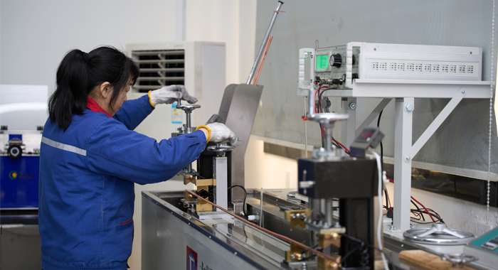
Quality Control
Control Cable 0.6/1 kV CVV-SWA to IEC 60502 Standard (2-16 core)
Raw Material Test
For the Control Cable 0.6/1 kV CVV-SWA to IEC 60502 Standard (2-16 core), raw material testing prioritises armour and shielding. Step 1: Assess copper conductor purity via spectrometry to achieve 99.99% per IEC 60228. Step 2: Test PVC insulation tensile strength (≥12.5 N/mm²) and elongation (≥150%) using mechanical testers. Step 3: Verify steel wire armour for tensile strength (≥400 N/mm²) and galvanisation thickness with micrometres. Step 4: Evaluate copper tape shield conductivity and thickness through resistivity analysis. Step 5: Conduct flame retardancy tests on sheaths via oxygen index (>27%). Step 6: Perform immersion tests on PVC in water, oils, and acids for 168 hours to check chemical resistance. Batch sampling (10%) and traceability documentation ensure rejection of non-compliant materials, aligning with IEC 60502 for armoured reliability.
Process inspection
Process inspection for the Control Cable 0.6/1 kV CVV-SWA to IEC 60502 Standard (2-16 core) emphasises armour integration. Step 1: Monitor conductor stranding tension with gauges every 100 meters for uniformity. Step 2: Scan insulation thickness (0.8mm nominal) using lasers, rejecting >5% deviations. Step 3: Inspect core assembly and numbering with automated vision systems. Step 4: Apply copper tape shield and verify overlap via ultrasonic testing. Step 5: Install steel wire armour and check bedding adhesion through torque tests. Step 6: Conduct in-line spark testing at 6 kV for insulation defects. Step 7: Verify outer sheath extrusion smoothness with profilometers. Step 8: Sample shifts for dimensional and mechanical integrity logging. This ISO 9001-compliant process detects issues early, ensuring IEC 60502 adherence and robust armoured protection in control cables.
Finished Product
Finished product testing of the Control Cable 0.6/1 kV CVV-SWA to IEC 60502 Standard (2-16 core) confirms armoured performance. Step 1: Execute voltage withstand at 3.5 kV for 5 minutes on insulation. Step 2: Measure resistance (>100 MΩ/km) with megohmmeters. Step 3: Test conductor resistance per IEC 60228. Step 4: Assess shielding effectiveness against EMI. Step 5: Evaluate armour impact resistance via drop tests. Step 6: Perform flame propagation (IEC 60332-1) and bending (8x diameter). Step 7: Cycle temperatures (-15°C to 90°C) for 48 hours. Step 8: Conduct final visual and electrical inspections. Calibrated equipment and 100% critical testing guarantee IEC 60502 compliance, delivering durable armoured cables for harsh applications.
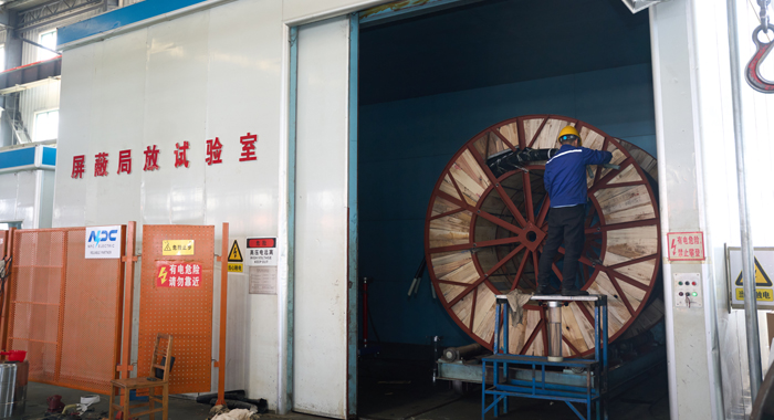
Application
The Control Cable 0.6/1 kV CVV-SWA to IEC 60502 Standard (2-16 core) is ideal for power station controls, industrial automation, substation circuits, and direct burial in construction sites. It offers armoured protection in wet, underground, or rodent-prone environments, ensuring reliable signal transmission for machinery and energy systems.


Technical Advantages
● 30+ years of manufacturing experience
● ISO and UL certified production
● Customized cable and transformer solutions


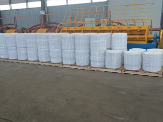
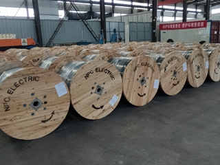
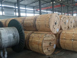
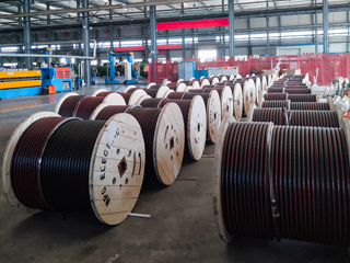
Product Packaging
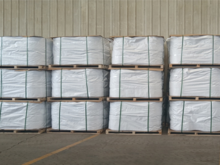
Wires and Cables packaging (1)
Wires and Cables packaging (2)
Wires and Cables packaging (3)
Wires and Cables packaging (4)
Wires and Cables packaging (5)
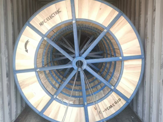
Wires and Cables packaging (6)
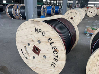
Wires and Cables packaging (7)
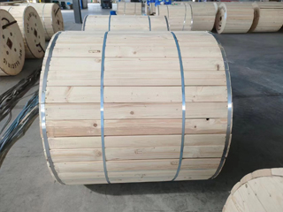
Wires and Cables packaging (8)
Related Products
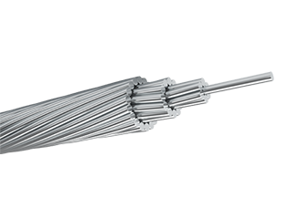
AMHERST AAAC Conductor Cable
AMHERST AAAC (All Aluminum Alloy Conductor) cables comply with ASTM B399 standards and offer high strength, good conductivity, and excellent corrosion resistance. With 300 mm² nominal area and 37-strand design, it uses heat-treated aluminum-magnesium-silicon alloy (6201-T81) for enhanced strength (295 MPa min) and conductivity (53% IACS min). Meeting ASTM B398, B399, IEC 61089, and BS EN 50182 standards, this cable handles ampacity up to 700A at 75°C and voltages up to 33kV. The all-alloy construction avoids bimetallic corrosion, providing better resistance in harsh conditions than ACSR. Reduced weight minimizes sag and installation expenses, supporting longer spans. The Amherst AAAC Conductor Cable delivers low electrical losses, high mechanical endurance, and excellent weather tolerance. Flame-retardant variants available. Perfect for urban grids, renewable projects, and coastal setups, it provides cost-effective, low-maintenance power delivery in overhead applications globally, excelling in reliability and lifespan over conventional conductors.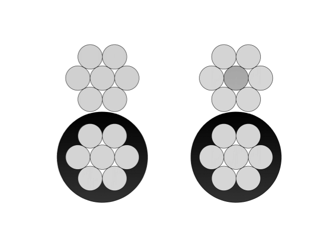
4 Spaniel Aluminum Conductor Duplex Overhead Service Drop Cable
Introducing the 4 Spaniel Duplex Service Drop Cable, a versatile overhead solution for low-voltage secondary distribution. Built with two 4 AWG aluminum conductors (7-strand) insulated with polyethylene or XLPE and formed into a duplex assembly, it meets ASTM and ICEA requirements for 600V service. The tough insulation offers outstanding protection against UV rays, moisture, tree contact, and abrasion. Compact duplex design provides self-support and easy pulling during installation. The 4 Spaniel Duplex Service Drop Cable supports efficient power transfer with low voltage drop and high durability in extreme temperatures. Popular for its lightweight construction and reduced installation time, it is the go-to choice for electricians and utilities. Widely deployed in housing developments, farm services, and temporary power setups, this cable ensures safe, long-lasting overhead connections from distribution transformers to customer service entrances worldwide.
AAAC Moose Conductor Cable
AAAC MOOSE conductor is manufactured in compliance with ASTM B399 or IEC 61089 standards, using high-strength aluminum alloy 6201-T81 for enhanced conductivity and corrosion resistance. Constructed entirely from high-strength aluminum alloy strands, it offers superior mechanical strength and corrosion resistance compared with traditional aluminum conductors. The Moose-size AAAC conductor is particularly suitable for long-span installations, providing excellent sag control and stable operation under heavy mechanical loads. Its all-alloy design ensures uniform conductivity and eliminates steel-related corrosion issues, extending service life in harsh environmental conditions. Manufactured under strict quality management systems, the AAAC Moose Conductor Cable complies with international standards and delivers reliable performance, simplified installation, and reduced lifecycle costs for utility and infrastructure projects worldwide.-AL-medium-voltage-power-cable.jpg)
RHZ1-OL(AS)-AL Medium Voltage Power Cable(8.7/15kV, 12/20kV, 18/30kV)
RHZ1-OL(AS)-AL Medium Voltage Power Cable (8.7/15kV, 12/20kV, 18/30kV) is a lightweight cable with enhanced fire retardancy for critical medium voltage applications. Featuring stranded aluminium conductors, cross-linked polyethylene (XLPE) insulation, metallic screen, and low smoke zero halogen (LSZH) outer sheath with advanced fire behavior (AS designation), it complies with UNE 21123-4 and higher CPR classifications. In fire scenarios, it produces very low smoke and no toxic gases. Aluminium construction reduces weight and costs while ensuring reliable current capacity. Superior partial discharge resistance, low dielectric losses, and high thermal stability provide efficient, long-lasting performance. Suitable for direct burial, ducts, or indoor use in high-safety areas. The RHZ1-OL(AS)-AL Medium Voltage Power Cable is perfect for utilities, hospitals, schools, tunnels, and infrastructure projects requiring economical, advanced fire-safe medium voltage cabling with exceptional life-safety features and durability worldwide.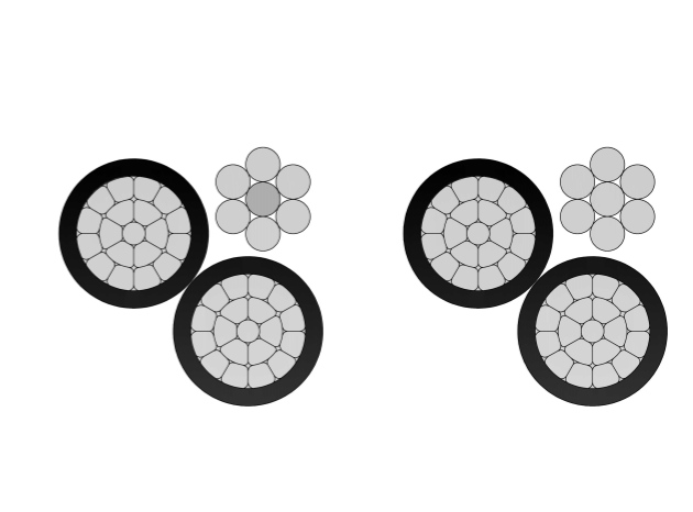
4 Oyster Aluminum Conductor Triplex Overhead Service Drop Cable
4-4-4 Oyster Aluminum Conductor Triplex Overhead Service Drop Cable provides high-quality overhead power transmission for utility-to-consumer connections. Constructed with compressed 1350-H19 aluminum phase conductors (#4 AWG), robust XLPE black insulation for enhanced thermal and environmental protection, and an AAC bare neutral (#4 AWG), it offers outstanding electrical efficiency, corrosion resistance, and durability in extreme weather. Designed for 600V applications (phase-to-phase) with conductor temps up to 90°C, it supports ~115A ampacity. Meets key standards including ASTM B-230/B-231/B-232 and ICEA S-76-474. Lightweight yet strong, this cable simplifies installation while ensuring long-term performance for service entrances.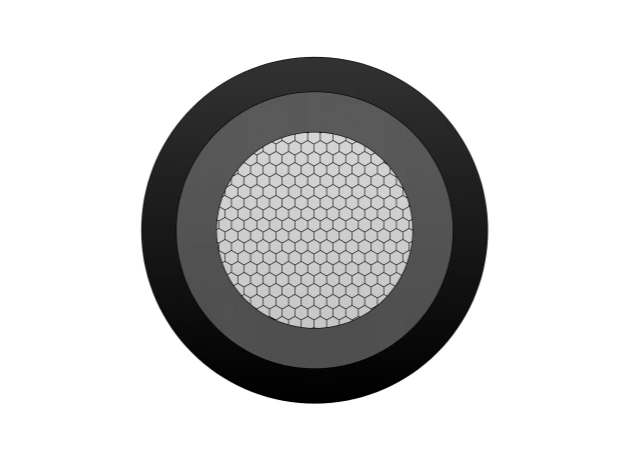
NSGAFÖU 1.8/3kV Rubber Cable
NSGAFÖU 1.8/3kV Rubber Cable is a robust, single-core flexible power cable engineered for extreme mechanical and environmental stresses in mining, tunneling, cranes, and mobile machinery. It features finely stranded tinned copper conductors (class 5) for superior flexibility and corrosion resistance, EPR (ethylene propylene rubber) insulation for excellent dielectric strength and 90°C continuous rating (250°C short-circuit), and a tough CPE (chlorinated polyethylene) or neoprene outer sheath providing outstanding oil resistance, flame retardancy (IEC 60332-1), abrasion/tear resistance, and weatherproofing. Compliant with DIN VDE 0250-813 / HD 22.16 S2 standards, it offers high mechanical strength, tight bending radii, and reliable performance in wet, oily, or abrasive conditions. The NSGAFÖU 1.8/3kV is ideal for trailing cables, reeling systems, and power connections where flexibility, durability, and safety are essential.FAQ From Customers
-
What are the advantages of power cables and overhead lines?(1) Reliable operation, because it is installed in a hidden place such as underground, it is less damaged by external forces, has less chance of failure, and the power supply is safe, and it will not cause harm to people; (2) The maintenance workload is small and frequent inspections are not required; (3) No need to erect towers; (4) Help improve power factor.
-
Which aspects should be considered when choosing the cross section of a power cable?(1) The long-term allowable working current of the cable; (2) Thermal stability once short circuited; (3) The voltage drop on the line cannot exceed the allowable working range.
-
What are the measures for cable fire prevention?(1) Use flame-retardant cables; (2) Use fireproof cable tray; (3) Use fireproof paint; (4) Fire partition walls and fire baffles are installed at cable tunnels, mezzanine exits, etc.; (5) Overhead cables should avoid oil pipelines and explosion-proof doors, otherwise local pipes or heat insulation and fire prevention measures should be taken.
-
What should be paid attention to during the transportation and handling of cables?(1) During transportation, loading and unloading, cables and cable reels should not be damaged. It is strictly forbidden to push the cable reels directly from the vehicle. Generally, cables should not be transported and stored flat. (2) Before transporting or rolling the cable reel, ensure that the cable reel is firm, the cable is wound tightly, the oil pipe between the oil-filled cable and the pressure oil tank should be fixed without damage, the pressure oil tank should be firm, and the pressure indication should meet the requirements.
-
What inspections should be carried out for the acceptance of cable lines?(1) The cable specifications should meet the regulations, the arrangement should be neat, no damage, and the signs should be complete, correct and clear; (2) The fixed bending radius of the cable, the related distance and the wiring of the metal sheath of the single-core power cable should meet the requirements; (3) The cable terminal and the middle head should not leak oil, and the installation should be firm. The oil pressure of the oil-filled cable and the meter setting should meet the requirements; (4) Good grounding; (5) The color of the cable terminal is correct, and the metal parts such as the bracket are completely painted; (6) There should be no debris in the cable trench, tunnel, and bridge, and the cover should be complete.
Welcome your inquiry
Honesty, Integrity, Frugality, Activeness and Passion