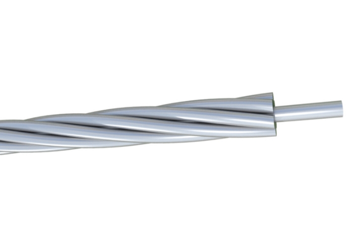

Galvanized Steel Conductor
The Galvanized Steel Conductor Cable Guard Wire offers robust mechanical protection for overhead power systems. Constructed from premium high-tensile steel wires with Class A or B hot-dip galvanization, it delivers exceptional resistance to rust, abrasion, and environmental stress. Meeting standards like ASTM A475 and BS EN 50189, this guard wire provides high breaking strength and flexibility for spanning long distances. Installed as an overhead shield, it prevents damage to conductors from external impacts, reducing downtime and maintenance costs. The uniform zinc layer ensures decades of service life even in coastal or polluted areas. Select our Galvanized Steel Conductor Cable Guard Wire for reliable overhead line guarding in electric utilities, telecommunications, and infrastructure projects worldwide.
- Standard ASTM A 475, BS 183, IEC 61089
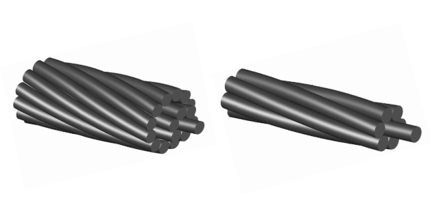
Construction
Technical Specifications
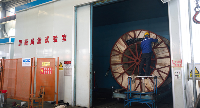
Quality Control
Application
Construction
Galvanized Steel Conductor
Conductor
Galvanized Clad steel wire earthwire/staywire/guywire/spacer cable (GSW): GSW Earth Wire, Stay Wire, Guy Wires, Spaces Cables, etc. are used as overhead ground wire or static wire on transmission lines, as pole or structure guy wires, and as messenger cable for field-erected aerial cable.
Technical Specifications
Galvanized Steel Conductor
IEC 60189
ASTM A475
BS 183
| Code No. | Section Area | No./Dia of Wire | Approx. Overall Diameter | Approx. Weight | Breaking Load | DC Resistance at 20°C Max. | |||
| S1A | S1B | S2A | S3A | ||||||
| mm² | No./mm | mm | kg/km | kN | kN | kN | kN | Ohm/km | |
| 4 | 27.1 | 7/2.22 | 6.66 | 213.3 | 36.3 | 33.6 | 39.3 | 43.9 | 7.1445 |
| 6.3 | 42.7 | 7/2.79 | 8.36 | 335.9 | 55.9 | 51.7 | 60.2 | 67.9 | 4.5362 |
| 10 | 67.8 | 7/3.51 | 10.53 | 553.2 | 87.4 | 80.7 | 93.5 | 103.0 | 2.8578 |
| 12.5 | 84.7 | 7/3.93 | 11.78 | 666.5 | 109.3 | 100.8 | 116.9 | 128.8 | 2.2862 |
| 16 | 108.4 | 7/4.44 | 13.32 | 853.1 | 139.9 | 129.0 | 199.7 | 164.8 | 1.7861 |
| 16 | 108.4 | 19/2.70 | 13.48 | 857.0 | 142.1 | 131.2 | 152.9 | 172.4 | 1.7944 |
| 25 | 169.4 | 19/3.37 | 16.85 | 1339.1 | 218.6 | 201.6 | 238.9 | 262.6 | 1.1484 |
| 40 | 271.1 | 19/4.26 | 21.31 | 2141.6 | 349.7 | 322.6 | 374.1 | 412.1 | 0.7177 |
| 40 | 271.1 | 37/3.05 | 21.38 | 2148.1 | 349.7 | 322.6 | 382.3 | 420.2 | 0.7196 |
| 63 | 427.0 | 37/3.83 | 26.83 | 3383.2 | 550.8 | 508.1 | 589.3 | 649.0 | 0.4569 |
| Nominal Dia. of Strand in.[mm] |
No. of Wires in Strand | Nominal Dia. of Coated Wires in Strand in.[mm] | Approximate Weight of Strand lb/1000ft[kg/km] |
Minimum Breaking Strength of Strand,lbf[KN] | |||||||||||||||
| Common Grade | Siemens-Martin Grade | High-Strength Grade | Extra High-Strength Grade | ||||||||||||||||
| 1/8 | 3.18 | 7 | 0.041 | 1.04 | 32 | 48 | 540 | 2.402 | 910 | 4.048 | 1 | 330 | 5.916 | 1 | 830 | 8.14 | |||
| 5/32 | 3.97 | 7 | 0.052 | 1.32 | 51 | 76 | 870 | 3.87 | 1 | 470 | 6.539 | 2 | 140 | 9.519 | 2 | 940 | 13.078 | ||
| 3/16 | 4.76 | 7 | 0.062 | 1.57 | 73 | 109 | 1 | 150 | 5.115 | 1 | 900 | 8.452 | 2 | 850 | 12.677 | 3 | 990 | 17.748 | |
| 3/16 | 4.76 | 7 | 0.065 | 1.65 | 80 | 119 | |||||||||||||
| 7/32 | 5.56 | 3 | 0.104 | 2.64 | 88 | 131 | 1 | 400 | 6.228 | 2 | 340 | 10.409 | 3 | 500 | 15.569 | 4 | 900 | 21.796 | |
| 7/32 | 5.56 | 7 | 0.072 | 1.83 | 98 | 146 | 1 | 540 | 6.85 | 2 | 560 | 11.387 | 3 | 850 | 17.126 | 5 | 400 | 24.02 | |
| 1/4 | 6.35 | 3 | 0.12 | 3.05 | 117 | 174 | 1 | 860 | 8.274 | 3 | 40 | 13.523 | 4 | 730 | 21.04 | 6 | 740 | 29.981 | |
| 1/4 | 6.35 | 3 | 0.12 | 3.05 | 117 | 174 | |||||||||||||
| 1/4 | 6.35 | 7 | 0.08 | 2.03 | 121 | 180 | 1 | 900 | 8.452 | 3 | 150 | 14.012 | 4 | 750 | 21.129 | 6 | 650 | 29.581 | |
| 9/32 | 7.14 | 3 | 0.13 | 3.3 | 137 | 204 | 2 | 80 | 9.252 | 3 | 380 | 15.035 | 5 | 260 | 23.398 | 7 | 500 | 33.362 | |
| 9/32 | 7.14 | 7 | 0.093 | 2.36 | 164 | 244 | 2 | 570 | 11.432 | 4 | 250 | 18.905 | 6 | 400 | 28.469 | 8 | 950 | 39.812 | |
| 5/16 | 7.94 | 3 | 0.145 | 3.68 | 171 | 255 | 2 | 490 | 11.076 | 4 | 90 | 18.193 | 6 | 350 | 28.246 | 9 | 100 | 40.479 | |
| 5/16 | 7.94 | 7 | 0.104 | 2.64 | 205 | 305 | 3 | 200 | 14.234 | 5 | 350 | 23.798 | 8 | 0 | 35.586 | 11 | 200 | 49.82 | |
| 5/16 | 7.94 | 7 | 1.109 | 2.77 | 225 | 335 | |||||||||||||
| 3/8 | 9.52 | 3 | 0.165 | 4.19 | 220 | 328 | 3 | 330 | 14.813 | 5 | 560 | 24.732 | 8 | 360 | 37.187 | 11 | 800 | 52.489 | |
| 3/8 | 9.52 | 7 | 0.12 | 3.05 | 273 | 407 | 4 | 250 | 18.905 | 6 | 950 | 30.915 | 10 | 800 | 48.04 | 15 | 400 | 68.503 | |
| 7/16 | 11.11 | 7 | 0.145 | 3.68 | 399 | 595 | 5 | 700 | 25.355 | 9 | 350 | 41.591 | 14 | 500 | 64.499 | 20 | 800 | 92.523 | |
| 1/2 | 12.7 | 7 | 0.165 | 4.19 | 517 | 770 | 7 | 400 | 32.917 | 12 | 100 | 53.823 | 18 | 800 | 83.627 | 26 | 900 | 119.657 | |
| 1/2 | 12.7 | 19 | 0.1 | 2.54 | 504 | 751 | 7 | 620 | 33.895 | 12 | 700 | 56.492 | 19 | 100 | 84.961 | 26 | 700 | 118.768 | |
| 9/16 | 14.29 | 7 | 0.188 | 4.78 | 671 | 1000 | 9 | 600 | 42.703 | 15 | 700 | 69.837 | 24 | 500 | 108.981 | 35 | 0 | 155.688 | |
| 9/16 | 14.29 | 19 | 0.113 | 2.87 | 637 | 949 | 9 | 640 | 42.881 | 16 | 100 | 71.616 | 24 | 100 | 107.202 | 33 | 700 | 14.905 | |
| 5/8 | 15.88 | 7 | 0.207 | 5.26 | 813 | 1211 | 11 | 600 | 51.599 | 19 | 100 | 84.961 | 29 | 600 | 131.667 | 42 | 400 | 188.605 | |
| 5/8 | 15.88 | 19 | 0.125 | 3.18 | 796 | 1186 | 11 | 0 | 48.93 | 18 | 100 | 80.513 | 28 | 100 | 124.995 | 40 | 200 | 178.819 | |
| 3/4 | 19.05 | 19 | 0.15 | 3.81 | 1 | 155 | 1721 | 16 | 0 | 71.172 | 26 | 200 | 116.543 | 40 | 800 | 181.487 | 58 | 300 | 259.331 |
| 7/8 | 22.22 | 19 | 0.177 | 4.5 | 1 | 581 | 2356 | 21 | 900 | 97.416 | 35 | 900 | 159.691 | 55 | 800 | 248.211 | 79 | 700 | 354.523 |
| 1 | 25.4 | 19 | 0.2 | 5.08 | 2 | 73 | 3089 | 28 | 700 | 127.664 | 47 | 0 | 209.066 | 73 | 200 | 325.61 | 104 | 500 | 464.839 |
| 1 | 25.4 | 37 | 0.143 | 3.63 | 2 | 57 | 3065 | 28 | 300 | 125.885 | 46 | 200 | 205.508 | 71 | 900 | 319.827 | 102 | 700 | 456.832 |
| 11/8 | 28.58 | 37 | 0.161 | 4.09 | 2 | 691 | 4010 | 36 | 0 | 160.136 | 58 | 900 | 262 | 91 | 600 | 407.457 | 130 | 800 | 581.827 |
| 11/4 | 31.75 | 37 | 0.179 | 4.55 | 3 | 248 | 4840 | 44 | 600 | 198.391 | 73 | 0 | 324.72 | 113 | 600 | 505.318 | 162 | 200 | 721.502 |
| No/Dia of Wire | Approx. Overall Diameter | Minimum Breaking Strength of Strand | Approx. Weight | ||||||
| Grade 350 | Grade 480 | Grade 700 | Grade 850 | Grade 1000 | Grade 1150 | Grade 1300 | |||
| No/mm | mm | kN | kN | kN | kN | kN | kN | kN | kg/km |
| 3/1 80 | 3.90 | 2.7 | 3.7 | 60.0 | |||||
| 3/2 65 | 5.70 | 5.8 | 8.0 | 130.0 | |||||
| 3/3 25 | 7.00 | 8.7 | 12.0 | 195.0 | |||||
| 3/4 00 | 8.60 | 13.2 | 18.1 | 295.0 | |||||
| 4/1 80 | 4.40 | 3.6 | 4.9 | 80.0 | |||||
| 4/2 65 | 6.40 | 7.7 | 10.6 | 172.0 | |||||
| 4/3 25 | 7.90 | 11.6 | 15.9 | 260.0 | |||||
| 4/4 00 | 9.70 | 17.6 | 24.1 | 35.2 | 390.0 | ||||
| 5/1 50 | 4.10 | 3.1 | 4.2 | 6.2 | 69.0 | ||||
| 5/1 80 | 4.90 | 4.5 | 6.1 | 8.9 | 95.0 | ||||
| 5/2 65 | 7.20 | 9.7 | 13.3 | 19.3 | 220.0 | ||||
| 5/3 25 | 8.80 | 14.5 | 19.9 | 29.0 | 320.0 | ||||
| 5/4 00 | 10.80 | 22.0 | 30.2 | 44.0 | 490.0 | ||||
| 7/0 56 | 1.70 | 0.6 | 0.8 | 1.2 | 1.7 | 2.0 | 2.2 | 14.0 | |
| 7/0 71 | 2.10 | 1.0 | 1.3 | 1.9 | 2.8 | 3.2 | 3.6 | 28.0 | |
| 7/0 85 | 2.60 | 1.4 | 1.9 | 2.8 | 4.0 | 4.6 | 5.2 | 31.0 | |
| 7/0 90 | 2.70 | 1.6 | 2.1 | 3.1 | 4.5 | 5.1 | 5.8 | 35.0 | |
| 7/1 00 | 3.00 | 1.9 | 2.6 | 3.9 | 5.5 | 6.3 | 7.2 | 43.0 | |
| 7/1 25 | 3.80 | 3.0 | 4.1 | 6.0 | 8.6 | 9.9 | 11.2 | 67.0 | |
| 7/1 40 | 4.20 | 3.8 | 5.2 | 7.5 | 9.2 | 10.8 | 12.4 | 14.0 | 84.0 |
| 7/RS* | 4.30 | 3.9 | 5.3 | 7.7 | 9.4 | 11.0 | 12.7 | 14.3 | 86.0 |
Quality Control
Galvanized Steel Conductor
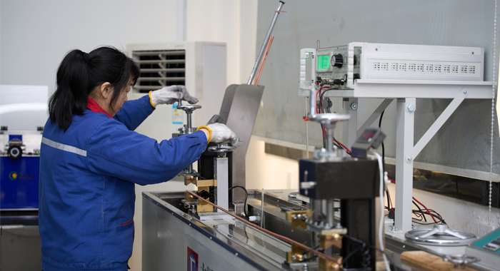
Raw Material Test
For the Galvanized Steel Conductor Cable Guard Wire, raw material testing starts with steel rod certification. Rods are sampled for microstructure analysis, hardness, and decarburization depth. Chemical elements are verified against specifications using optical emission spectroscopy. Mechanical tests include yield strength, tensile strength, and bend tests. Galvanizing flux and zinc are checked for impurities. The wire rod surface is inspected for cracks via magnetic particle testing. The step-by-step process: receipt documentation review, sampling protocol, physical/mechanical testing, chemical composition confirmation, surface defect evaluation, and material approval stamp. This comprehensive evaluation secures premium inputs, establishing the base for the Galvanized Steel Conductor Cable Guard Wire's superior strength and galvanizing performance.
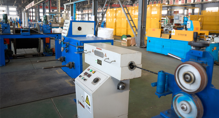
Process inspection
Process inspection in Galvanized Steel Conductor Cable Guard Wire manufacturing involves real-time quality checks. Individual wire drawing stages monitor reduction ratio and ovality with laser micrometers. Stranding line inspects pre-former operation, tension balance, and strand compaction. Galvanizing process controls line speed, bath composition, and cooling rate for optimal coating adhesion. In-process coating thickness sampling uses Elcometer gauges. Mandrel wrap tests on drawn wires verify ductility. Defect marking and removal occur immediately. Critical steps: material feed verification, drawing die wear check, stranding parameter logging, galvanizing immersion timing, post-process adhesion sampling, and reel inspection. This ensures the Galvanized Steel Conductor Cable Guard Wire maintains precise dimensions, uniform coating, and structural integrity.
Finished Product
Completed Galvanized Steel Conductor Cable Guard Wire is rigorously tested before shipment. Key routines: ultimate tensile strength test with recorded load-elongation curve, zinc coating uniformity and mass determination, and diameter tolerance measurement across strands. Adhesion is tested by wrapping around a mandrel without flaking. Corrosion resistance via accelerated tests, if required. The detailed process: reel sampling, test length preparation, machine setup and calibration, progressive loading to break, coating stripping and weighing, visual/post-failure analysis, and documentation. Additional verifications include weight per kilometer and packaging. Passing all ensures the Galvanized Steel Conductor Cable Guard Wire delivers specified mechanical properties, durable galvanization, and safe overhead guarding performance.
Application
Ideal for protecting overhead transmission and distribution conductors from mechanical damage. Commonly applied on utility poles, towers, and crossings in forests, highways, and urban areas to prevent outages caused by external impacts.


Technical Advantages
● 30+ years of manufacturing experience
● ISO and UL certified production
● Customized cable and transformer solutions


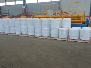
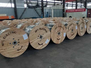
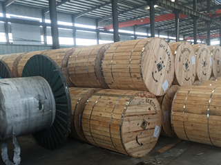
Product Packaging
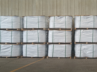
Wires and Cables packaging (1)
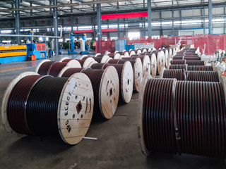
Wires and Cables packaging (2)
Wires and Cables packaging (3)
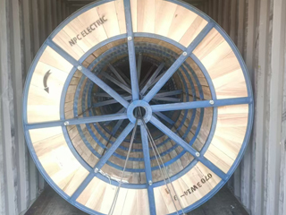
Wires and Cables packaging (4)
Wires and Cables packaging (5)
Wires and Cables packaging (6)
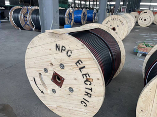
Wires and Cables packaging (7)
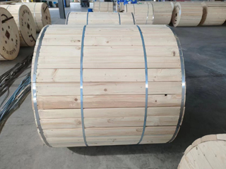
Wires and Cables packaging (8)
Related Products

RHZ1-2OL-AL Medium Voltage Power Cable(8.7/15kV, 12/20kV, 18/30kV)
RHZ1-2OL-AL Medium Voltage Power Cable (8.7/15kV, 12/20kV, 18/30kV) is an economical, fire-safe cable for medium voltage distribution. Featuring stranded aluminium conductors, cross-linked polyethylene (XLPE) insulation, metallic screen, and low smoke zero halogen (LSZH) outer sheath, it complies with UNE 21123-4 and CPR standards. In fire conditions, the LSZH sheath emits minimal smoke and no toxic halogen gases, ensuring safety in populated areas. Lightweight aluminium reduces costs and handling effort while providing reliable current capacity. Superior partial discharge resistance, low dielectric losses, and high thermal stability guarantee efficient, long-lasting performance. Suitable for direct burial, ducts, or indoor installations. The RHZ1-2OL-AL Medium Voltage Power Cable is widely used in utilities, hospitals, schools, tunnels, and infrastructure projects requiring cost-effective, environmentally friendly medium voltage cabling with enhanced fire safety and durability worldwide.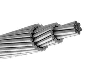
2 AWG SPARROW ACSR Conductor Cable
The 2 AWG SPARROW ACSR (Aluminum Conductor Steel Reinforced) cable, compliant with ASTM B232, ABNT NBR 7270/88, and IEC 61089 standards, is engineered for dependable performance in overhead transmission and distribution systems. Featuring a stranded 1350-H19 aluminum conductor for excellent electrical conductivity and a single galvanized steel core for enhanced mechanical strength, this cable is ideal for medium to long-span installations in suburban, agricultural, and utility networks. With a voltage rating of up to 25 kV, an operating temperature range of -10°C to +75°C, and a short-circuit tolerance of up to 150°C (5s), the SPARROW ACSR ensures reliable conductivity, corrosion resistance, and durability under wind and ice loading. Its lightweight, bare aluminum design with a corrosion-resistant steel core simplifies installation and ensures a long service life in diverse outdoor environments. Ampacity is calculated under standard conditions (conductor temperature: 75°C; ambient temperature: 25°C; wind speed: 1 m/s; full sun exposure).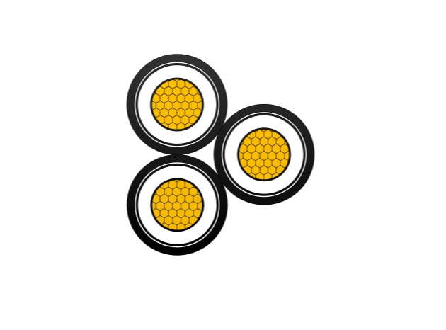
FR-N30XA8E-R 18/30kV Cable Gen to NF C 33-226 - Cu/XLPE/MDPE
The NF C 33-226 Cu-XLPE-MDPE 18/30kV Cable is a robust medium voltage power cable designed for safe and reliable energy transmission in fixed installations. It features a Class 2 stranded copper conductor, cross-linked polyethylene (XLPE) insulation, and a medium-density polyethylene (MDPE) outer sheath, ensuring outstanding electrical conductivity, insulation integrity, and mechanical protection. Complying with NF C 33-226, IEC 60502-2, and EN 60228, this cable is ideal for power distribution in industrial plants, substations, municipal grids, and commercial facilities. It provides excellent resistance to water (AD7) and UV radiation (ISO 4892), while being halogen-free (IEC/EN 60754-1) to ensure environmental and operational safety. With a voltage rating of 18/30 (36)kV and maximum operating temperature of 90°C, the Cu-XLPE-MDPE construction guarantees stable, efficient, and long-lasting performance in medium- and high-voltage networks.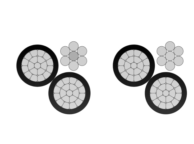
2/0 Triton Aluminum Conductor Triplex Overhead Service Drop Cable
The 2/0 Triton Aluminum Conductor Triplex Overhead Service Drop Cable is engineered for reliable overhead electrical service from utility distribution lines to residential and commercial buildings. The cable consists of two insulated aluminum phase conductors twisted around a bare aluminum neutral messenger, providing balanced electrical performance and strong mechanical support. Manufactured from high-purity aluminum and weather-resistant insulation compounds, the 2/0 Triton Aluminum Conductor Triplex Overhead Service Drop Cable delivers low electrical resistance, excellent corrosion resistance, and long-term durability in outdoor environments. Its lightweight construction simplifies handling and installation while maintaining the tensile strength required for aerial service. The cable is designed to perform under UV exposure, wind loading, and temperature variation. Comprehensive quality control and systematic testing are applied throughout production to ensure compliance with utility standards and dependable field performance.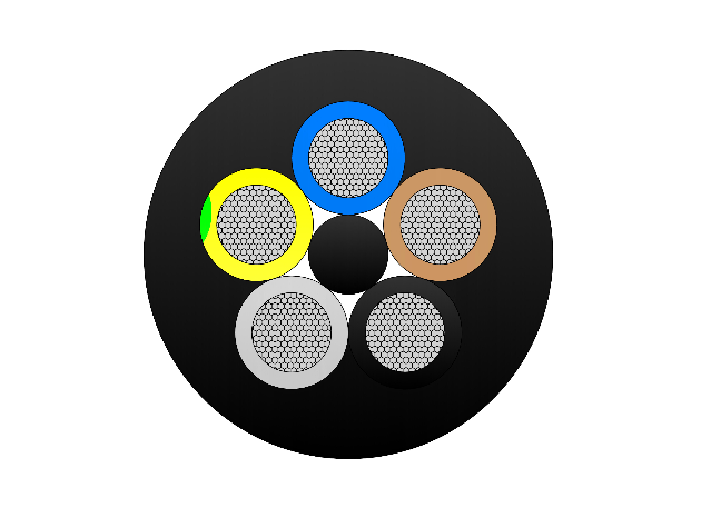
(N)TSCGECEWOU 8.7/15kV and 12/20kV ATB Cable (Ground Check Conductor)
The (N)TSCGECEWOU 8.7/15kV and 12/20kV ATB (Ground Check Conductor) Cable is a flexible medium-voltage cable enhanced with anti-torsion braid (ATB) and ground check conductor (GCC) for superior stability and safety monitoring in mining. It comprises tinned class 5 copper phase conductors, semi-conductive screens, EPR insulation for reliable dielectric/thermal performance, copper braid screen, control conductors, dedicated ground check conductor for fault detection, anti-torsion braid to reduce twisting under heavy loads, and a robust rubber sheath resistant to oils, flames, abrasion, and mechanical damage. Compliant with DIN VDE 0250, it offers high flexibility, torsional strength, and EMC protection for dynamic applications. The (N)TSCGECEWOU ATB GCC ensures dependable higher-voltage MV power with ground continuity monitoring for heavy mobile machinery such as excavators, draglines, and tunnel boring equipment in opencast and underground mining.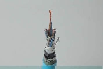
Instrumentation Cables—XLPE Insulated,Individual &Overall Screened,Unarmoured PVC Sheathed Cables(CU/XLPE/IOSCR/PVC)
Instrumentation Cables are multi-conductor cables that carry and transport low-voltage electrical signals. These low-voltage signals are used to control and monitor electrical power systems. Instrumentation cables have many different industrial applications that include broadcasting, equipment control, such as drilling and pumping in the oil and gas industry, and data transfer, which includes analog and digital signals. They are manufactured according to the BS EN 50288-7 and BS EN 50288-1 standards to ensure quality. Depending on the application, instrumentation cables can be insulated with PVC or XLPE; the cables can be armoured or unarmoured. The sheathing materials can be of PVC, LSZH, or PE. The cables can have additional flame retardant or flame retardant properties, and they can be manufactured with special protections such as lead sheaths, or DRYLAM or AIRBAG technology.FAQ From Customers
-
What are the advantages of power cables and overhead lines?(1) Reliable operation, because it is installed in a hidden place such as underground, it is less damaged by external forces, has less chance of failure, and the power supply is safe, and it will not cause harm to people; (2) The maintenance workload is small and frequent inspections are not required; (3) No need to erect towers; (4) Help improve power factor.
-
Which aspects should be considered when choosing the cross section of a power cable?(1) The long-term allowable working current of the cable; (2) Thermal stability once short circuited; (3) The voltage drop on the line cannot exceed the allowable working range.
-
What are the measures for cable fire prevention?(1) Use flame-retardant cables; (2) Use fireproof cable tray; (3) Use fireproof paint; (4) Fire partition walls and fire baffles are installed at cable tunnels, mezzanine exits, etc.; (5) Overhead cables should avoid oil pipelines and explosion-proof doors, otherwise local pipes or heat insulation and fire prevention measures should be taken.
-
What should be paid attention to during the transportation and handling of cables?(1) During transportation, loading and unloading, cables and cable reels should not be damaged. It is strictly forbidden to push the cable reels directly from the vehicle. Generally, cables should not be transported and stored flat. (2) Before transporting or rolling the cable reel, ensure that the cable reel is firm, the cable is wound tightly, the oil pipe between the oil-filled cable and the pressure oil tank should be fixed without damage, the pressure oil tank should be firm, and the pressure indication should meet the requirements.
-
What inspections should be carried out for the acceptance of cable lines?(1) The cable specifications should meet the regulations, the arrangement should be neat, no damage, and the signs should be complete, correct and clear; (2) The fixed bending radius of the cable, the related distance and the wiring of the metal sheath of the single-core power cable should meet the requirements; (3) The cable terminal and the middle head should not leak oil, and the installation should be firm. The oil pressure of the oil-filled cable and the meter setting should meet the requirements; (4) Good grounding; (5) The color of the cable terminal is correct, and the metal parts such as the bracket are completely painted; (6) There should be no debris in the cable trench, tunnel, and bridge, and the cover should be complete.
Welcome your inquiry
Honesty, Integrity, Frugality, Activeness and Passion