


High Voltage Power Cable
NPC Electric High Voltage Power Cable is engineered for reliable transmission of electricity at voltages from 35kV to 500kV. Featuring copper or aluminum conductors, cross-linked polyethylene (XLPE) insulation, metallic screening, and a robust outer sheath, this cable minimizes losses and ensures long-term performance in demanding environments. Designed to meet international standards like IEC 60840 and IEC 62067, it offers excellent electrical properties, mechanical strength, and resistance to moisture, chemicals, and thermal stress. Whether for underground burial, submarine applications, or overhead lines, our High Voltage Power Cable delivers superior efficiency and safety. With low dielectric losses and high breakdown strength, it supports modern power grids, renewable energy integration, and industrial power distribution. Choose our cables for minimal maintenance, extended service life, and compliance with global safety norms.
- Standard IEC 60840, IEC 62067
Construction
Technical Specifications
Quality Control
Application
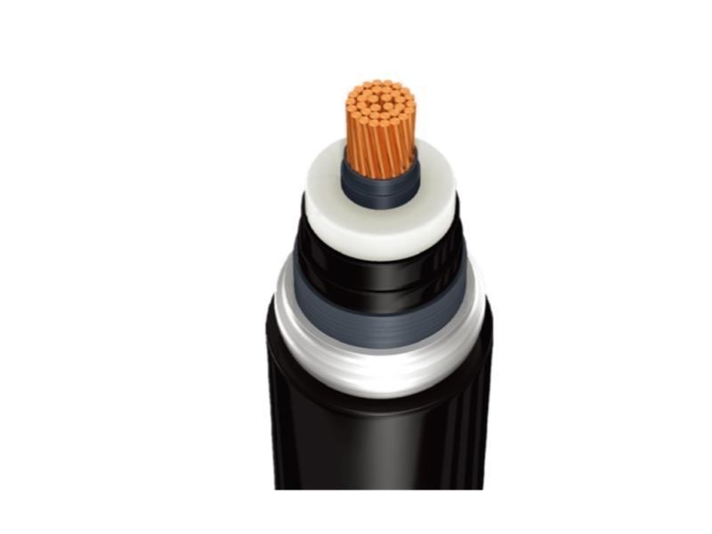
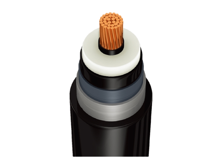
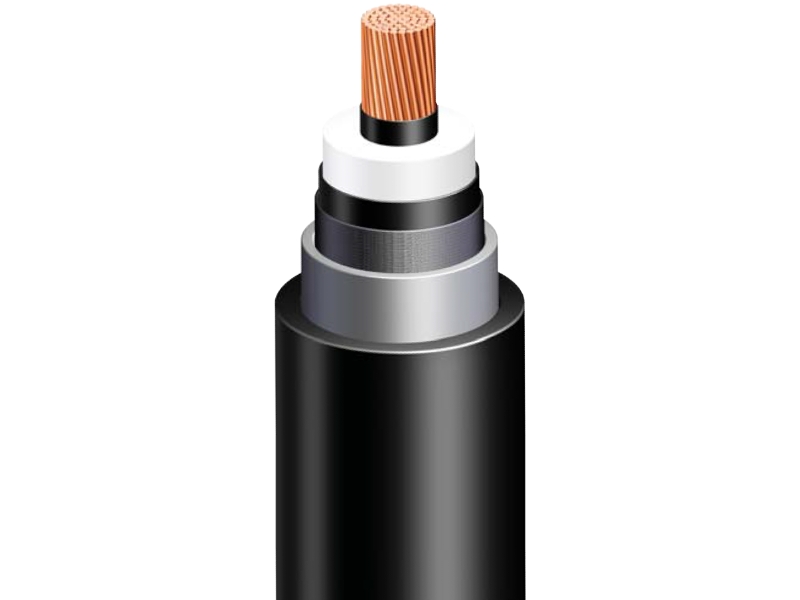
Construction
High Voltage Power Cable
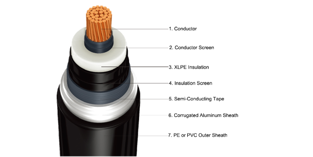
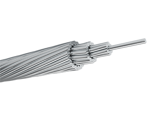
Conductor
The conductor consists of annealed copper or hard aluminum stranded wires and is classified into three (3) major types of concentric, compacted circular, and segmental compacted circular.
Insulation
The insulation material is extruded cross-linked polyethylene. The conductor screen, the insulation, and the insulation screen mentioned to the following clause are extruded simultaneously in one process to ensure that the screen and insulation are intimately bonded together and free from all possibilities of voids between layers.
Conductor Screen
The conductor screen consists of an extruded semi-conducting polyethylene to minimize electrical stresses due to the stranded configuration of the conductor. The semi-conducting material used for the conductor screen has no deleterious effect on the conductor. Semi-conducting tape is sometimes applied as a separator.
Insulation Screen
The insulation screen is provided over the insulation by extruding the semi-conducting compound concentrically and circularly to minimize the possibility of ionization on the outer surface of the dielectric.
Metallic Screen
The metallic screen consists of the wire shield, the corrugated aluminum sheath, or the lead sheath. The corrugated aluminum sheath and the lead sheath are also adopted where the surface of the duct is poor and where moisture is high.
Outer Sheath
To protect the metallic sheath from electrical or chemical corrosion, it is covered by PE or PVC.
Technical Specifications
High Voltage Power Cable
36/66 (72.5) kV with Aluminum Sheath
36/66 (72.5) kV with Lead Sheath
36/66 (72.5) kV with Copper Wire Shield
64/110 (123) kV with Aluminum Sheath
64/110 (123) kV with Lead Sheath
64/110 (123) kV with Copper Wire Shield
76/132 (145) kV with Aluminum Sheath
76/132 (145) kV with Lead Sheath
76/132 (145) kV with Copper Wire Shield
87/161 (170) kV with Aluminum Sheath
87/161 (170) kV with Lead Sheath
87/161 (170) kV with Copper Wire Shield
127/230 (245) kV with Aluminum Sheath
127/230 (245) kV with Lead Sheath
127/230 (245) kV with Copper Wire Shield
| Continuous Current Ratings for Single Circuit (A) | ||||
|---|---|---|---|---|
| Cross-Sectional Area(mm2) | Direct Buried | Pipe Duct | In Air | |
| Trefoil | Flat(S=2D) | |||
| 240 | 524 | 491 | 598 | 671 |
| 300 | 592 | 556 | 682 | 770 |
| 400 | 671 | 631 | 781 | 888 |
| 500 | 762 | 714 | 894 | 1025 |
| 630 | 878 | 808 | 1023 | 1187 |
| 800 | 965 | 928 | 1150 | 1355 |
| 1000 | 1119 | 1075 | 1361 | 1615 |
| 1200 | 1198 | 1146 | 1460 | 1745 |
| 1600 | 1352 | 1357 | 1654 | 2030 |
| 2000 | 1468 | 1475 | 1800 | 2273 |
| Conductor |
Thickness of Conductor Screen Approx. |
Thickness of Insulation |
Thickness of Insulation Screen Approx. | Thickness of Aluminum Sheath |
Thickness of Outer Sheath |
Outer Diameter of Cable |
Weight of Cable |
Max. DC Conductor Resistance at 20 °C | Capacitance | ||
| Cross-Sectional Area | Shape | Diameter | |||||||||
| mm² | mm | mm | mm | mm | mm | mm | mm | kg/m | Ω/km | μF/km | |
| 240 | Compact Round Stranded | 18.1 | 1.0 | 11.0 | 1.0 | 1.6 | 3.5 | 69 | 5.5 | 0.0754 | 0.20 |
| 300 | 20.4 | 1.0 | 11.0 | 1.0 | 1.6 | 3.5 | 72 | 6.3 | 0.0601 | 0.21 | |
| 400 | 23.2 | 1.0 | 11.0 | 1.0 | 1.7 | 3.5 | 75 | 7.2 | 0.0470 | 0.23 | |
| 500 | 26.3 | 1.0 | 11.0 | 1.0 | 1.8 | 4.0 | 79 | 8.6 | 0.0366 | 0.25 | |
| 630 | 30.2 | 1.0 | 11.0 | 1.0 | 1.8 | 4.0 | 83 | 10.1 | 0.0283 | 0.28 | |
| 800 | 34.0 | 1.0 | 11.0 | 1.0 | 1.9 | 4.0 | 87 | 12 | 0.0221 | 0.30 | |
| 1000 | Segment Stranded (Miliken) | 38.7 | 1.0 | 11.0 | 1.0 | 2.0 | 4.0 | 92 | 14.4 | 0.0176 | 0.33 |
| 1200 | 41.8 | 1.0 | 11.0 | 1.0 | 2.1 | 4.5 | 98 | 16.7 | 0.0151 | 0.36 | |
| 1600 | 48.1 | 1.0 | 11.0 | 1.0 | 2.2 | 4.5 | 105 | 20.9 | 0.0113 | 0.40 | |
| 2000 | 54.3 | 1.0 | 11.0 | 1.0 | 2.4 | 4.5 | 112 | 25.4 | 0.0090 | 0.44 | |
| Continuous Current Ratings for Single Circuit (A) | ||||
|---|---|---|---|---|
| Cross-Sectional Area(mm2) | Direct Buried | Pipe Duct | In Air | |
| Trefoil | Flat(S=2D) | |||
| 240 | 535 | 525 | 621 | 706 |
| 300 | 606 | 567 | 710 | 810 |
| 400 | 691 | 646 | 822 | 942 |
| 500 | 787 | 733 | 951 | 1098 |
| 630 | 898 | 833 | 1096 | 1274 |
| 800 | 1008 | 958 | 1243 | 1462 |
| 1000 | 1184 | 1121 | 1505 | 1759 |
| 1200 | 1282 | 1208 | 1648 | 1938 |
| 1600 | 1469 | 1434 | 1906 | 2282 |
| 2000 | 1626 | 1585 | 2130 | 2597 |
| Conductor |
Thickness of Conductor Screen Approx. |
Thickness of Insulation |
Thickness of Insulation Screen Approx. | Thickness of Aluminum Sheath |
Thickness of Outer Sheath |
Outer Diameter of Cable |
Weight of Cable |
Max. DC Conductor Resistance at 20 °C | Capacitance | ||
| Cross-Sectional Area | Shape | Diameter | |||||||||
| mm² | mm | mm | mm | mm | mm | mm | mm | kg/m | Ω/km | μF/km | |
| 240 | Compact Round Stranded | 18.1 | 1.0 | 11.0 | 1.0 | 2.1 | 3.5 | 62 | 8.1 | 0.0754 | 0.20 |
| 300 | 20.4 | 1.0 | 11.0 | 1.0 | 2.2 | 3.5 | 64 | 9.1 | 0.0601 | 0.21 | |
| 400 | 23.2 | 1.0 | 11.0 | 1.0 | 2.3 | 3.5 | 67 | 10.5 | 0.0470 | 0.23 | |
| 500 | 26.3 | 1.0 | 11.0 | 1.0 | 2.4 | 4.0 | 72 | 12.5 | 0.0366 | 0.25 | |
| 630 | 30.2 | 1.0 | 11.0 | 1.0 | 2.4 | 4.0 | 76 | 14.2 | 0.0283 | 0.28 | |
| 800 | 34.0 | 1.0 | 11.0 | 1.0 | 2.6 | 4.0 | 80 | 16.9 | 0.0221 | 0.30 | |
| 1000 | Segment Stranded (Miliken) | 38.7 | 1.0 | 11.0 | 1.0 | 2.7 | 4.0 | 85 | 19.9 | 0.0176 | 0.33 |
| 1200 | 41.8 | 1.0 | 11.0 | 1.0 | 2.8 | 4.5 | 91 | 23.0 | 0.0151 | 0.36 | |
| 1600 | 48.1 | 1.0 | 11.0 | 1.0 | 3.0 | 4.5 | 97 | 28.0 | 0.0113 | 0.40 | |
| 2000 | 54.3 | 1.0 | 11.0 | 1.0 | 3.2 | 4.5 | 104 | 33.4 | 0.0090 | 0.44 | |
| Continuous Current Ratings for Single Circuit (A) | ||||
|---|---|---|---|---|
| Cross-Sectional Area(mm2) | Direct Buried | Pipe Duct | In Air | |
| Trefoil | Flat(S=2D) | |||
| 240 | 530 | 483 | 606 | 692 |
| 300 | 599 | 544 | 693 | 795 |
| 400 | 683 | 616 | 802 | 925 |
| 500 | 780 | 729 | 929 | 1075 |
| 630 | 886 | 828 | 1066 | 1247 |
| 800 | 997 | 929 | 1210 | 1432 |
| 1000 | 1173 | 1087 | 1473 | 1728 |
| 1200 | 1270 | 1173 | 1611 | 1894 |
| 1600 | 1465 | 1375 | 1883 | 2245 |
| 2000 | 1627 | 1530 | 2111 | 2556 |
| Conductor |
Thickness of Conductor Screen Approx. |
Thickness of Insulation |
Thickness of Insulation Screen Approx. | Thickness of Aluminum Sheath |
Thickness of Outer Sheath |
Outer Diameter of Cable |
Weight of Cable |
Max. DC Conductor Resistance at 20 °C | Capacitance | ||
| Cross-Sectional Area | Shape | Diameter | |||||||||
| mm² | mm | mm | mm | mm | mm | mm | mm | kg/m | Ω/km | μF/km | |
| 240 | Compact Round Stranded | 18.1 | 1.0 | 11.0 | 1.0 | 1.2×40 | 3.5 | 58 | 4.4 | 0.0754 | 0.20 |
| 300 | 20.4 | 1.0 | 11.0 | 1.0 | 1.2×40 | 3.5 | 60 | 5.1 | 0.0601 | 0.21 | |
| 400 | 23.2 | 1.0 | 11.0 | 1.0 | 1.2×40 | 3.5 | 63 | 5.9 | 0.0470 | 0.23 | |
| 500 | 26.3 | 1.0 | 11.0 | 1.0 | 1.2×40 | 4.0 | 66 | 7.2 | 0.0366 | 0.25 | |
| 630 | 30.2 | 1.0 | 11.0 | 1.0 | 1.2×40 | 4.0 | 71 | 8.6 | 0.0283 | 0.28 | |
| 800 | 34.0 | 1.0 | 11.0 | 1.0 | 1.2×40 | 4.0 | 75 | 10.4 | 0.0221 | 0.30 | |
| 1000 | Segment Stranded (Miliken) | 38.7 | 1.0 | 11.0 | 1.0 | 1.2×40 | 4.0 | 80 | 12.7 | 0.0176 | 0.33 |
| 1200 | 41.8 | 1.0 | 11.0 | 1.0 | 1.2×40 | 4.5 | 85 | 14.7 | 0.0151 | 0.36 | |
| 1600 | 48.1 | 1.0 | 11.0 | 1.0 | 1.2×40 | 4.5 | 91 | 18.7 | 0.0113 | 0.40 | |
| 2000 | 54.3 | 1.0 | 11.0 | 1.0 | 1.2×40 | 4.5 | 97 | 22.7 | 0.0090 | 0.44 | |
| Continuous Current Ratings for Single Circuit (A) | ||||
|---|---|---|---|---|
| Cross-Sectional Area(mm2) | Direct Buried | Pipe Duct | In Air | |
| Trefoil | Flat(S=2D) | |||
| 240 | 533 | 498 | 617 | 692 |
| 300 | 602 | 563 | 705 | 794 |
| 400 | 687 | 654 | 816 | 923 |
| 500 | 782 | 744 | 939 | 1068 |
| 630 | 891 | 846 | 1083 | 1243 |
| 800 | 1001 | 949 | 1229 | 1425 |
| 1000 | 1176 | 1108 | 1468 | 1718 |
| 1200 | 1269 | 1235 | 1612 | 1871 |
| 1600 | 1455 | 1415 | 1870 | 2206 |
| 2000 | 1609 | 1562 | 2087 | 2505 |
| 2500 | 1695 | 1647 | 2201 | 2642 |
| Conductor |
Thickness of Conductor Screen Approx. |
Thickness of Insulation |
Thickness of Insulation Screen Approx. | Thickness of Aluminum Sheath |
Thickness of Outer Sheath |
Outer Diameter of Cable |
Weight of Cable |
Max. DC Conductor Resistance at 20 °C | Capacitance | ||
| Cross-Sectional Area | Shape | Diameter | |||||||||
| mm² | mm | mm | mm | mm | mm | mm | mm | kg/m | Ω/km | μF/km | |
| 240 | Compact Round Stranded | 18.1 | 1.2 | 14.0 | 1.0 | 2.3 | 3.5 | 68 | 9.6 | 0.0754 | 0.17 |
| 300 | 20.4 | 1.2 | 14.0 | 1.0 | 2.4 | 3.5 | 71 | 10.9 | 0.0601 | 0.18 | |
| 400 | 23.2 | 1.2 | 14.0 | 1.0 | 2.5 | 3.5 | 74 | 12.3 | 0.0470 | 0.20 | |
| 500 | 26.3 | 1.2 | 14.0 | 1.0 | 2.5 | 4.0 | 78 | 13.8 | 0.0366 | 0.21 | |
| 630 | 30.2 | 1.2 | 14.0 | 1.0 | 2.6 | 4.0 | 82 | 16.0 | 0.0283 | 0.23 | |
| 800 | 34.0 | 1.2 | 14.0 | 1.0 | 2.7 | 4.0 | 86 | 18.5 | 0.0221 | 0.25 | |
| 1000 | Segment Stranded (Miliken) | 38.7 | 1.2 | 14.0 | 1.0 | 2.9 | 4.0 | 92 | 21.9 | 0.0176 | 0.28 |
| 1200 | 41.8 | 1.2 | 14.0 | 1.0 | 3.0 | 4.5 | 97 | 24.7 | 0.0151 | 0.30 | |
| 1600 | 48.1 | 1.2 | 14.0 | 1.0 | 3.2 | 4.5 | 103 | 30.1 | 0.0113 | 0.33 | |
| 2000 | 54.3 | 1.2 | 14.0 | 1.0 | 3.4 | 4.5 | 110 | 35.7 | 0.0090 | 0.36 | |
| 2500 | 63.0 | 1.2 | 14.0 | 1.0 | 3.6 | 4.5 | 118 | 42.0 | 0.0072 | 0.40 | |
| Continuous Current Ratings for Single Circuit (A) | ||||
|---|---|---|---|---|
| Cross-Sectional Area(mm2) | Direct Buried | Pipe Duct | In Air | |
| Trefoil | Flat(S=2D) | |||
| 240 | 528 | 495 | 605 | 682 |
| 300 | 597 | 559 | 692 | 793 |
| 400 | 681 | 650 | 800 | 909 |
| 500 | 775 | 739 | 922 | 1053 |
| 630 | 884 | 841 | 1065 | 1226 |
| 800 | 994 | 945 | 1208 | 1406 |
| 1000 | 1169 | 1106 | 1465 | 1695 |
| 1200 | 1264 | 1231 | 1595 | 1849 |
| 1600 | 1456 | 1415 | 1860 | 2185 |
| 2000 | 1618 | 1570 | 2089 | 2487 |
| 2500 | 1706 | 1656 | 2203 | 2623 |
| Conductor |
Thickness of Conductor Screen Approx. |
Thickness of Insulation |
Thickness of Insulation Screen Approx. | Thickness of Aluminum Sheath |
Thickness of Outer Sheath |
Outer Diameter of Cable |
Weight of Cable |
Max. DC Conductor Resistance at 20 °C | Capacitance | ||
| Cross-Sectional Area | Shape | Diameter | |||||||||
| mm² | mm | mm | mm | mm | mm | mm | mm | kg/m | Ω/km | μF/km | |
| 240 | Compact Round Stranded | 18.1 | 1.2 | 14.0 | 1.0 | 1.2×40 | 3.5 | 64 | 5.0 | 0.0754 | 0.17 |
| 300 | 20.4 | 1.2 | 14.0 | 1.0 | 1.2×40 | 3.5 | 66 | 5.7 | 0.0601 | 0.18 | |
| 400 | 23.2 | 1.2 | 14.0 | 1.0 | 1.2×40 | 3.5 | 69 | 6.6 | 0.0470 | 0.20 | |
| 500 | 26.3 | 1.2 | 14.0 | 1.0 | 1.2×40 | 4.0 | 73 | 7.9 | 0.0366 | 0.21 | |
| 630 | 30.2 | 1.2 | 14.0 | 1.0 | 1.2×40 | 4.0 | 77 | 9.4 | 0.0283 | 0.23 | |
| 800 | 34.0 | 1.2 | 14.0 | 1.0 | 1.2×40 | 4.0 | 81 | 11.2 | 0.0221 | 0.25 | |
| 1000 | Segment Stranded (Miliken) | 38.7 | 1.2 | 14.0 | 1.0 | 1.2×40 | 4.0 | 86 | 13.6 | 0.0176 | 0.28 |
| 1200 | 41.8 | 1.2 | 14.0 | 1.0 | 1.2×40 | 4.5 | 91 | 15.6 | 0.0151 | 0.30 | |
| 1600 | 48.1 | 1.2 | 14.0 | 1.0 | 1.2×40 | 4.5 | 97 | 19.6 | 0.0113 | 0.33 | |
| 2000 | 54.3 | 1.2 | 14.0 | 1.0 | 1.2×40 | 4.5 | 103 | 23.7 | 0.0090 | 0.36 | |
| 2500 | 63.0 | 1.2 | 14.0 | 1.0 | 1.2×40 | 4.5 | 111 | 29.0 | 0.0072 | 0.40 | |
| Continuous Current Ratings for Single Circuit (A) | ||||
|---|---|---|---|---|
| Cross-Sectional Area(mm2) | Direct Buried | Pipe Duct | In Air | |
| Trefoil | Flat(S=2D) | |||
| 240 | 519 | 486 | 589 | 649 |
| 300 | 585 | 547 | 671 | 742 |
| 400 | 665 | 635 | 770 | 858 |
| 500 | 755 | 716 | 883 | 992 |
| 630 | 856 | 814 | 1011 | 1151 |
| 800 | 956 | 942 | 1137 | 1313 |
| 1000 | 1103 | 1093 | 1333 | 1555 |
| 1200 | 1185 | 1170 | 1439 | 1695 |
| 1600 | 1333 | 1324 | 1627 | 1972 |
| 2000 | 1452 | 1435 | 1777 | 2211 |
| 2500 | 1530 | 1512 | 1872 | 2330 |
| Conductor |
Thickness of Conductor Screen Approx. |
Thickness of Insulation |
Thickness of Insulation Screen Approx. | Thickness of Aluminum Sheath |
Thickness of Outer Sheath |
Outer Diameter of Cable |
Weight of Cable |
Max. DC Conductor Resistance at 20 °C | Capacitance | ||
| Cross-Sectional Area | Shape | Diameter | |||||||||
| mm² | mm | mm | mm | mm | mm | mm | mm | kg/m | Ω/km | μF/km | |
| 240 | Compact Round Stranded | 18.1 | 1.5 | 16.0 | 1.3 | 1.8 | 4.5 | 83 | 7.1 | 0.0754 | 0.16 |
| 300 | 20.4 | 1.5 | 16.0 | 1.3 | 1.8 | 4.5 | 86 | 7.9 | 0.0601 | 0.17 | |
| 400 | 23.2 | 1.5 | 16.0 | 1.3 | 1.9 | 4.5 | 89 | 8.9 | 0.0470 | 0.18 | |
| 500 | 26.3 | 1.5 | 16.0 | 1.3 | 2.0 | 4.5 | 92 | 10.2 | 0.0366 | 0.20 | |
| 630 | 30.2 | 1.5 | 16.0 | 1.3 | 2.1 | 4.5 | 97 | 11.9 | 0.0283 | 0.21 | |
| 800 | 34.0 | 1.5 | 16.0 | 1.3 | 2.2 | 4.5 | 101 | 14.0 | 0.0221 | 0.23 | |
| 1000 | Segment Stranded (Miliken) | 38.7 | 1.5 | 16.0 | 1.3 | 2.2 | 4.5 | 106 | 16.6 | 0.0176 | 0.25 |
| 1200 | 41.8 | 1.5 | 16.0 | 1.3 | 2.3 | 4.5 | 110 | 18.6 | 0.0151 | 0.27 | |
| 1600 | 48.1 | 1.5 | 16.0 | 1.3 | 2.4 | 4.5 | 116 | 22.9 | 0.0113 | 0.30 | |
| 2000 | 54.3 | 1.5 | 16.0 | 1.3 | 2.6 | 4.5 | 124 | 27.4 | 0.0090 | 0.32 | |
| 2500 | 63.0 | 1.5 | 16.0 | 1.3 | 2.8 | 4.5 | 131 | 34.3 | 0.0072 | 0.36 | |
| Continuous Current Ratings for Single Circuit (A) | ||||
|---|---|---|---|---|
| Cross-Sectional Area(mm2) | Direct Buried | Pipe Duct | In Air | |
| Trefoil | Flat(S=2D) | |||
| 240 | 530 | 495 | 612 | 679 |
| 300 | 600 | 559 | 702 | 781 |
| 400 | 684 | 636 | 808 | 904 |
| 500 | 780 | 727 | 934 | 1050 |
| 630 | 889 | 840 | 1077 | 1222 |
| 800 | 997 | 941 | 1222 | 1400 |
| 1000 | 1170 | 1100 | 1469 | 1681 |
| 1200 | 1264 | 1226 | 1599 | 1842 |
| 1600 | 1449 | 1404 | 1853 | 2168 |
| 2000 | 1600 | 1548 | 2064 | 2460 |
| 2500 | 1686 | 1631 | 2175 | 2592 |
| Conductor |
Thickness of Conductor Screen Approx. |
Thickness of Insulation |
Thickness of Insulation Screen Approx. | Thickness of Aluminum Sheath |
Thickness of Outer Sheath |
Outer Diameter of Cable |
Weight of Cable |
Max. DC Conductor Resistance at 20 °C | Capacitance | ||
| Cross-Sectional Area | Shape | Diameter | |||||||||
| mm² | mm | mm | mm | mm | mm | mm | mm | kg/m | Ω/km | μF/km | |
| 240 | Compact Round Stranded | 18.1 | 1.5 | 16.0 | 1.3 | 2.4 | 4.5 | 76 | 11.2 | 0.0754 | 0.16 |
| 300 | 20.4 | 1.5 | 16.0 | 1.3 | 2.5 | 4.5 | 78 | 12.3 | 0.0601 | 0.17 | |
| 400 | 23.2 | 1.5 | 16.0 | 1.3 | 2.6 | 4.5 | 81 | 13.8 | 0.0470 | 0.18 | |
| 500 | 26.3 | 1.5 | 16.0 | 1.3 | 2.7 | 4.5 | 85 | 15.6 | 0.0366 | 0.20 | |
| 630 | 30.2 | 1.5 | 16.0 | 1.3 | 2.7 | 4.5 | 88 | 17.5 | 0.0283 | 0.21 | |
| 800 | Segment Stranded (Miliken) | 34.0 | 1.5 | 16.0 | 1.3 | 2.9 | 4.5 | 93 | 20.4 | 0.0221 | 0.23 |
| 1000 | 38.7 | 1.5 | 16.0 | 1.3 | 3.0 | 4.5 | 98 | 23.6 | 0.0176 | 0.25 | |
| 1200 | 41.8 | 1.5 | 16.0 | 1.3 | 3.1 | 4.5 | 102 | 26.5 | 0.0151 | 0.27 | |
| 1600 | 48.1 | 1.5 | 16.0 | 1.3 | 3.3 | 4.5 | 108 | 31.7 | 0.0113 | 0.30 | |
| 2000 | 54.3 | 1.5 | 16.0 | 1.3 | 3.5 | 4.5 | 115 | 37.7 | 0.0090 | 0.32 | |
| 2500 | 63.0 | 1.5 | 16.0 | 1.3 | 3.7 | 4.5 | 123 | 44.3 | 0.0072 | 0.36 | |
| Continuous Current Ratings for Single Circuit (A) | ||||
|---|---|---|---|---|
| Cross-Sectional Area(mm2) | Direct Buried | Pipe Duct | In Air | |
| Trefoil | Flat(S=2D) | |||
| 240 | 530 | 495 | 612 | 679 |
| 300 | 600 | 559 | 702 | 781 |
| 400 | 684 | 636 | 808 | 904 |
| 500 | 780 | 727 | 934 | 1050 |
| 630 | 889 | 840 | 1077 | 1222 |
| 800 | 997 | 941 | 1222 | 1400 |
| 1000 | 1170 | 1100 | 1469 | 1681 |
| 1200 | 1264 | 1226 | 1599 | 1842 |
| 1600 | 1449 | 1404 | 1853 | 2168 |
| 2000 | 1600 | 1548 | 2064 | 2460 |
| 2500 | 1686 | 1631 | 2175 | 2592 |
| Conductor |
Thickness of Conductor Screen Approx. |
Thickness of Insulation |
Thickness of Insulation Screen Approx. | Thickness of Aluminum Sheath |
Thickness of Outer Sheath |
Outer Diameter of Cable |
Weight of Cable |
Max. DC Conductor Resistance at 20 °C | Capacitance | ||
| Cross-Sectional Area | Shape | Diameter | |||||||||
| mm² | mm | mm | mm | mm | mm | mm | mm | kg/m | Ω/km | μF/km | |
| 240 | Compact Round Stranded | 18.1 | 1.5 | 16.0 | 1.3 | 2.4 | 4.5 | 76 | 11.2 | 0.0754 | 0.16 |
| 300 | 20.4 | 1.5 | 16.0 | 1.3 | 2.5 | 4.5 | 78 | 12.3 | 0.0601 | 0.17 | |
| 400 | 23.2 | 1.5 | 16.0 | 1.3 | 2.6 | 4.5 | 81 | 13.8 | 0.0470 | 0.18 | |
| 500 | 26.3 | 1.5 | 16.0 | 1.3 | 2.7 | 4.5 | 85 | 15.6 | 0.0366 | 0.20 | |
| 630 | 30.2 | 1.5 | 16.0 | 1.3 | 2.7 | 4.5 | 88 | 17.5 | 0.0283 | 0.21 | |
| 800 | 34.0 | 1.5 | 16.0 | 1.3 | 2.9 | 4.5 | 93 | 20.4 | 0.0221 | 0.23 | |
| 1000 | Segment Stranded (Miliken) | 38.7 | 1.5 | 16.0 | 1.3 | 3.0 | 4.5 | 98 | 23.6 | 0.0176 | 0.25 |
| 1200 | 41.8 | 1.5 | 16.0 | 1.3 | 3.1 | 4.5 | 102 | 26.5 | 0.0151 | 0.27 | |
| 1600 | 48.1 | 1.5 | 16.0 | 1.3 | 3.3 | 4.5 | 108 | 31.7 | 0.0113 | 0.30 | |
| 2000 | 54.3 | 1.5 | 16.0 | 1.3 | 3.5 | 4.5 | 115 | 37.7 | 0.0090 | 0.32 | |
| 2500 | 63.0 | 1.5 | 16.0 | 1.3 | 3.7 | 4.5 | 123 | 44.3 | 0.0072 | 0.36 | |
| Continuous Current Ratings for Single Circuit (A) | ||||
|---|---|---|---|---|
| Cross-Sectional Area(mm2) | Direct Buried | Pipe Duct | In Air | |
| Trefoil | Flat(S=2D) | |||
| 300 | 584 | 558 | 669 | 740 |
| 400 | 664 | 634 | 768 | 855 |
| 500 | 754 | 718 | 879 | 988 |
| 630 | 853 | 811 | 1009 | 1146 |
| 800 | 953 | 938 | 1134 | 1307 |
| 1000 | 1100 | 1087 | 1328 | 1548 |
| 1200 | 1179 | 1163 | 1429 | 1684 |
| 1600 | 1331 | 1311 | 1627 | 1967 |
| 2000 | 1447 | 1485 | 1774 | 2199 |
| 2500 | 1523 | 1563 | 1868 | 2315 |
| Conductor |
Thickness of Conductor Screen Approx. |
Thickness of Insulation |
Thickness of Insulation Screen Approx. | Thickness of Aluminum Sheath |
Thickness of Outer Sheath |
Outer Diameter of Cable |
Weight of Cable |
Max. DC Conductor Resistance at 20 °C | Capacitance | ||
| Cross-Sectional Area | Shape | Diameter | |||||||||
| mm² | mm | mm | mm | mm | mm | mm | mm | kg/m | Ω/km | μF/km | |
| 300 | Compact Round Stranded | 20.4 | 1.5 | 17.0 | 1.3 | 1.9 | 4.5 | 87 | 8.4 | 0.0601 | 0.16 |
| 400 | 23.2 | 1.5 | 17.0 | 1.3 | 1.9 | 4.5 | 91 | 9.4 | 0.0470 | 0.18 | |
| 500 | 26.3 | 1.5 | 17.0 | 1.3 | 2.0 | 4.5 | 94 | 10.7 | 0.0366 | 0.19 | |
| 630 | 30.2 | 1.5 | 17.0 | 1.3 | 2.1 | 4.5 | 98 | 12.3 | 0.0283 | 0.21 | |
| 800 | 34.0 | 1.5 | 17.0 | 1.3 | 2.2 | 4.5 | 102 | 14.4 | 0.0221 | 0.22 | |
| 1000 | Segment Stranded (Miliken) | 38.7 | 1.5 | 17.0 | 1.3 | 2.3 | 4.5 | 108 | 17.0 | 0.0176 | 0.24 |
| 1200 | 41.8 | 1.5 | 17.0 | 1.3 | 2.3 | 4.5 | 111 | 19.0 | 0.0151 | 0.26 | |
| 1600 | 48.1 | 1.5 | 17.0 | 1.3 | 2.5 | 4.5 | 119 | 23.5 | 0.0113 | 0.28 | |
| 2000 | 54.3 | 1.5 | 17.0 | 1.3 | 2.6 | 4.5 | 125 | 28.0 | 0.0090 | 0.31 | |
| 2500 | 63.0 | 1.5 | 17.0 | 1.3 | 2.8 | 4.5 | 134 | 34.5 | 0.0072 | 0.34 | |
| Continuous Current Ratings for Single Circuit (A) | ||||
|---|---|---|---|---|
| Cross-Sectional Area(mm2) | Direct Buried | Pipe Duct | In Air | |
| Trefoil | Flat(S=2D) | |||
| 300 | 598 | 557 | 698 | 775 |
| 400 | 682 | 648 | 805 | 898 |
| 500 | 777 | 736 | 928 | 1042 |
| 630 | 886 | 836 | 1073 | 1214 |
| 800 | 996 | 939 | 1218 | 1391 |
| 1000 | 1168 | 1131 | 1464 | 1670 |
| 1200 | 1259 | 1221 | 1589 | 1825 |
| 1600 | 1445 | 1398 | 1845 | 2152 |
| 2000 | 1597 | 1541 | 2060 | 2445 |
| 2500 | 1681 | 1622 | 2169 | 2574 |
| Conductor |
Thickness of Conductor Screen Approx. |
Thickness of Insulation |
Thickness of Insulation Screen Approx. | Thickness of Aluminum Sheath |
Thickness of Outer Sheath |
Outer Diameter of Cable |
Weight of Cable |
Max. DC Conductor Resistance at 20 °C | Capacitance | ||
| Cross-Sectional Area | Shape | Diameter | |||||||||
| mm² | mm | mm | mm | mm | mm | mm | mm | kg/m | Ω/km | μF/km | |
| 300 | Compact Round Stranded | 20.4 | 1.5 | 17.0 | 1.3 | 2.5 | 4.5 | 80 | 12.5 | 0.0601 | 0.16 |
| 400 | 23.2 | 1.5 | 17.0 | 1.3 | 2.6 | 4.5 | 83 | 14.0 | 0.0470 | 0.18 | |
| 500 | 26.3 | 1.5 | 17.0 | 1.3 | 2.7 | 4.5 | 86 | 15.7 | 0.0366 | 0.19 | |
| 630 | 30.2 | 1.5 | 17.0 | 1.3 | 2.8 | 4.5 | 80 | 18.0 | 0.0283 | 0.21 | |
| 800 | 34.0 | 1.5 | 17.0 | 1.3 | 2.9 | 4.5 | 94 | 20.5 | 0.0221 | 0.22 | |
| 1000 | Segment Stranded (Miliken) | 38.7 | 1.5 | 17.0 | 1.3 | 3.0 | 4.5 | 100 | 23.8 | 0.0176 | 0.24 |
| 1200 | 41.8 | 1.5 | 17.0 | 1.3 | 3.2 | 4.5 | 103 | 26.7 | 0.0151 | 0.26 | |
| 1600 | 48.1 | 1.5 | 17.0 | 1.3 | 3.4 | 4.5 | 110 | 32.2 | 0.0113 | 0.28 | |
| 2000 | 54.3 | 1.5 | 17.0 | 1.3 | 3.6 | 4.5 | 116 | 37.9 | 0.0090 | 0.31 | |
| 2500 | 63.0 | 1.5 | 17.0 | 1.3 | 3.7 | 4.5 | 124 | 44.9 | 0.0072 | 0.34 | |
| Continuous Current Ratings for Single Circuit (A) | ||||
|---|---|---|---|---|
| Cross-Sectional Area(mm2) | Direct Buried | Pipe Duct | In Air | |
| Trefoil | Flat(S=2D) | |||
| 300 | 591 | 553 | 684 | 765 |
| 400 | 673 | 629 | 789 | 887 |
| 500 | 766 | 713 | 907 | 1027 |
| 630 | 871 | 829 | 1043 | 1193 |
| 800 | 977 | 928 | 1181 | 1367 |
| 1000 | 1143 | 1081 | 1415 | 1639 |
| 1200 | 1232 | 1208 | 1535 | 1790 |
| 1600 | 1404 | 1382 | 1765 | 2100 |
| 2000 | 1554 | 1523 | 1973 | 2384 |
| 2500 | 1636 | 1603 | 2077 | 2510 |
| Conductor |
Thickness of Conductor Screen Approx. |
Thickness of Insulation |
Thickness of Insulation Screen Approx. | Thickness of Aluminum Sheath |
Thickness of Outer Sheath |
Outer Diameter of Cable |
Weight of Cable |
Max. DC Conductor Resistance at 20 °C | Capacitance | ||
| Cross-Sectional Area | Shape | Diameter | |||||||||
| mm² | mm | mm | mm | mm | mm | mm | mm | kg/m | Ω/km | μF/km | |
| 300 | Compact Round Stranded | 20.4 | 1.5 | 17.0 | 1.3 | 1.5×80 | 4.5 | 72 | 6.3 | 0.0601 | 0.21 |
| 400 | 23.2 | 1.5 | 17.0 | 1.3 | 1.5×80 | 4.5 | 75 | 7.2 | 0.0470 | 0.23 | |
| 500 | 26.3 | 1.5 | 17.0 | 1.3 | 1.5×80 | 4.5 | 79 | 8.6 | 0.0366 | 0.25 | |
| 630 | 30.2 | 1.5 | 17.0 | 1.3 | 1.5×80 | 4.5 | 83 | 10.1 | 0.0283 | 0.28 | |
| 800 | 34.0 | 1.5 | 17.0 | 1.3 | 1.5×80 | 4.5 | 87 | 12.0 | 0.0221 | 0.30 | |
| 1000 | Segment Stranded (Miliken) | 38.7 | 1.5 | 17.0 | 1.3 | 1.5×80 | 4.5 | 92 | 14.4 | 0.0176 | 0.33 |
| 1200 | 41.8 | 1.5 | 17.0 | 1.3 | 1.5×80 | 4.5 | 98 | 16.7 | 0.0151 | 0.36 | |
| 1600 | 48.1 | 1.5 | 17.0 | 1.3 | 1.5×80 | 4.5 | 105 | 20.9 | 0.0113 | 0.40 | |
| 2000 | 54.3 | 1.5 | 17.0 | 1.3 | 1.5×80 | 4.5 | 112 | 25.4 | 0.0090 | 0.44 | |
| 2500 | 63.0 | 1.5 | 17.0 | 1.3 | 1.5×80 | 4.5 | 118 | 31.1 | 0.0072 | 0.34 | |
| Continuous Current Ratings for Single Circuit (A) | ||||
|---|---|---|---|---|
| Cross-Sectional Area(mm2) | Direct Buried | Pipe Duct | In Air | |
| Trefoil | Flat(S=2D) | |||
| 400 | 657 | 641 | 757 | 836 |
| 500 | 745 | 725 | 866 | 962 |
| 630 | 843 | 822 | 989 | 1111 |
| 800 | 943 | 916 | 1116 | 1268 |
| 1000 | 1090 | 1057 | 1310 | 1505 |
| 1200 | 1165 | 1131 | 1403 | 1631 |
| 1600 | 1316 | 1322 | 1596 | 1902 |
| 2000 | 1438 | 1440 | 1758 | 2143 |
| 2500 | 1512 | 1514 | 1849 | 2254 |
| Conductor |
Thickness of Conductor Screen Approx. |
Thickness of Insulation |
Thickness of Insulation Screen Approx. | Thickness of Aluminum Sheath |
Thickness of Outer Sheath |
Outer Diameter of Cable |
Weight of Cable |
Max. DC Conductor Resistance at 20 °C | Capacitance | ||
| Cross-Sectional Area | Shape | Diameter | |||||||||
| mm² | mm | mm | mm | mm | mm | mm | mm | kg/m | Ω/km | μF/km | |
| 400 | Compact Round Stranded | 23.2 | 1.5 | 23.0 | 1.3 | 2.2 | 4.5 | 104 | 11.0 | 0.0470 | 0.14 |
| 500 | 26.3 | 1.5 | 23.0 | 1.3 | 2.3 | 4.5 | 108 | 12.1 | 0.0366 | 0.15 | |
| 630 | 30.2 | 1.5 | 23.0 | 1.3 | 2.4 | 4.5 | 112 | 14.2 | 0.0283 | 0.17 | |
| 800 | 34.0 | 1.5 | 23.0 | 1.3 | 2.4 | 4.5 | 116 | 15.8 | 0.0221 | 0.18 | |
| 1000 | 38.7 | 1.5 | 23.0 | 1.3 | 2.4 | 4.5 | 116 | 15.8 | 0.0221 | 0.18 | |
| 1200 | Segment Stranded (Miliken) | 41.8 | 1.5 | 23.0 | 1.3 | 2.6 | 5.0 | 126 | 21.5 | 0.0151 | 0.21 |
| 1600 | 48.1 | 1.5 | 23.0 | 1.3 | 2.7 | 5.0 | 133 | 26.0 | 0.0113 | 0.23 | |
| 2000 | 54.3 | 1.5 | 23.0 | 1.3 | 2.8 | 5.0 | 139 | 30.7 | 0.0090 | 0.24 | |
| 2500 | 63.0 | 1.5 | 23.0 | 1.3 | 3.0 | 5.0 | 148 | 37.8 | 0.0072 | 0.27 | |
| Continuous Current Ratings for Single Circuit (A) | ||||
|---|---|---|---|---|
| Cross-Sectional Area(mm2) | Direct Buried | Pipe Duct | In Air | |
| Trefoil | Flat(S=2D) | |||
| 400 | 676 | 638 | 793 | 871 |
| 500 | 770 | 745 | 914 | 1010 |
| 630 | 876 | 847 | 1054 | 1173 |
| 800 | 986 | 950 | 1196 | 1343 |
| 1000 | 1153 | 1108 | 1429 | 1606 |
| 1200 | 1243 | 1194 | 1552 | 1757 |
| 1600 | 1424 | 1401 | 1797 | 2068 |
| 2000 | 1571 | 1545 | 2004 | 2342 |
| 2500 | 1652 | 1625 | 2108 | 2463 |
| Conductor |
Thickness of Conductor Screen Approx. |
Thickness of Insulation |
Thickness of Insulation Screen Approx. | Thickness of Aluminum Sheath |
Thickness of Outer Sheath |
Outer Diameter of Cable |
Weight of Cable |
Max. DC Conductor Resistance at 20 °C | Capacitance | ||
| Cross-Sectional Area | Shape | Diameter | |||||||||
| mm² | mm | mm | mm | mm | mm | mm | mm | kg/m | Ω/km | μF/km | |
| 400 | Compact Round Stranded | 23.2 | 1.5 | 23.0 | 1.3 | 3.2 | 4.5 | 96 | 17.9 | 0.0470 | 0.14 |
| 500 | 26.3 | 1.5 | 23.0 | 1.3 | 3.3 | 4.5 | 100 | 19.7 | 0.0366 | 0.15 | |
| 630 | 30.2 | 1.5 | 23.0 | 1.3 | 3.4 | 4.5 | 104 | 22.1 | 0.0283 | 0.17 | |
| 800 | 34.0 | 1.5 | 23.0 | 1.3 | 3.5 | 4.5 | 108 | 24.8 | 0.0221 | 0.18 | |
| 1000 | Segment Stranded (Miliken) | 38.7 | 1.5 | 23.0 | 1.3 | 3.6 | 5.0 | 114 | 28.8 | 0.0176 | 0.20 |
| 1200 | 41.8 | 1.5 | 23.0 | 1.3 | 3.9 | 5.0 | 118 | 32.3 | 0.0151 | 0.21 | |
| 1600 | 48.1 | 1.5 | 23.0 | 1.3 | 4.1 | 5.0 | 124 | 38.2 | 0.0113 | 0.23 | |
| 2000 | 54.3 | 1.5 | 23.0 | 1.3 | 4.2 | 5.0 | 130 | 43.8 | 0.0090 | 0.24 | |
| 2500 | 63.0 | 1.5 | 23.0 | 1.3 | 4.4 | 5.0 | 148 | 52.5 | 0.0072 | 0.27 | |
| Continuous Current Ratings for Single Circuit (A) | ||||
|---|---|---|---|---|
| Cross-Sectional Area(mm2) | Direct Buried | Pipe Duct | In Air | |
| Trefoil | Flat(S=2D) | |||
| 400 | 668 | 634 | 779 | 863 |
| 500 | 759 | 719 | 895 | 998 |
| 630 | 864 | 842 | 1031 | 1159 |
| 800 | 970 | 944 | 1167 | 1326 |
| 1000 | 1131 | 1100 | 1390 | 1583 |
| 1200 | 1221 | 1185 | 1512 | 1733 |
| 1600 | 1397 | 1354 | 1750 | 2040 |
| 2000 | 1543 | 1489 | 1950 | 2309 |
| 2500 | 1623 | 1566 | 2051 | 2429 |
| Conductor |
Thickness of Conductor Screen Approx. |
Thickness of Insulation |
Thickness of Insulation Screen Approx. | Thickness of Aluminum Sheath |
Thickness of Outer Sheath |
Outer Diameter of Cable |
Weight of Cable |
Max. DC Conductor Resistance at 20 °C | Capacitance | ||
| Cross-Sectional Area | Shape | Diameter | |||||||||
| mm² | mm | mm | mm | mm | mm | mm | mm | kg/m | Ω/km | μF/km | |
| 400 | Compact Round Stranded | 23.2 | 1.5 | 23.0 | 1.3 | 1.5×80 | 4.5 | 91 | 10.0 | 0.0470 | 0.14 |
| 500 | 26.3 | 1.5 | 23.0 | 1.3 | 1.5×80 | 4.5 | 94 | 11.2 | 0.0366 | 0.15 | |
| 630 | 30.2 | 1.5 | 23.0 | 1.3 | 1.5×80 | 4.5 | 98 | 12.8 | 0.0283 | 0.17 | |
| 800 | 34.0 | 1.5 | 23.0 | 1.3 | 1.5×80 | 4.5 | 102 | 14.8 | 0.0221 | 0.18 | |
| 1000 | Segment Stranded (Miliken) | 38.7 | 1.5 | 23.0 | 1.3 | 1.5×80 | 5.0 | 107 | 17.2 | 0.0176 | 0.20 |
| 1200 | 41.8 | 1.5 | 23.0 | 1.3 | 1.5×80 | 5.0 | 110 | 19.2 | 0.0151 | 0.21 | |
| 1600 | 48.1 | 1.5 | 23.0 | 1.3 | 1.5×80 | 5.0 | 116 | 23.3 | 0.0113 | 0.23 | |
| 2000 | 54.3 | 1.5 | 23.0 | 1.3 | 1.5×80 | 5.0 | 123 | 27.6 | 0.0090 | 0.24 | |
| 2500 | 63.0 | 1.5 | 23.0 | 1.3 | 1.5×80 | 5.0 | 132 | 33.9 | 0.0072 | 0.27 | |
Quality Control
High Voltage Power Cable
Raw Material Test
For our High Voltage Power Cable, raw material testing is critical to ensure quality from the start. The process begins with incoming inspection of conductor materials (copper/aluminum) for purity, conductivity, and tensile strength per ASTM/IEC standards. Insulation compounds like XLPE are tested for density, melt flow index, and contamination using hot set and elongation tests. Semiconducting layers undergo resistivity checks to prevent field stress. Sheath materials are evaluated for abrasion resistance and environmental stress cracking. Samples are subjected to thermal aging, oxidation induction time (OIT), and impurity analysis via microscopy. Partial discharge (PD) inception voltage is measured on extruded samples. All tests follow strict protocols: visual inspection, dimensional verification, chemical composition analysis, and mechanical/electrical property verification.
Process inspection
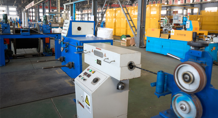
During the manufacturing of the High Voltage Power Cable, process inspection ensures consistency at every stage. Triple extrusion of conductor shield, XLPE insulation, and insulation shield is monitored for thickness uniformity and concentricity using online X-ray or laser gauges. Curing in dry nitrogen prevents voids, with real-time temperature and pressure control. The metallic screening application is checked for continuity and bonding. The outer sheath extrusion undergoes spark testing for pinholes. In-process partial discharge (PD) monitoring detects defects immediately. Dimensional checks, eccentricity measurements, and surface smoothness inspections occur at key points. Degassing removes by-products post-crosslinking. Sampling for hot set tests verifies the crosslinking degree. The step-by-step flow includes: material feeding verification, extrusion parameter logging, cooling process control, and interim electrical tests.
Finished Product
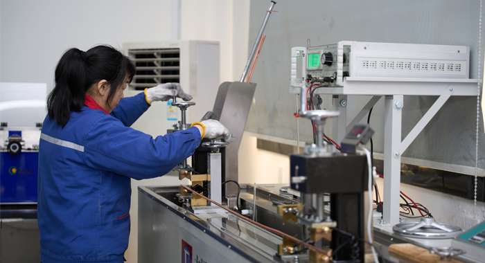
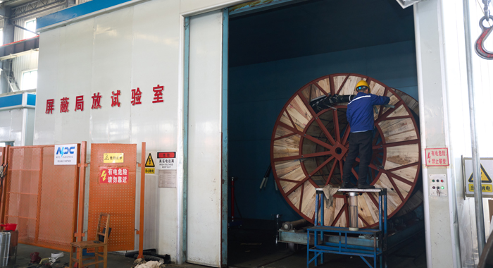
The finished High Voltage Power Cable undergoes comprehensive testing to validate performance. Routine tests include conductor resistance measurement, high voltage AC withstand (up to 1.7U0), and partial discharge (PD) detection below 5pC per IEC standards. Insulation thickness and sheath integrity are verified. Type tests cover bending, thermal cycling, impulse withstand, and water penetration. Samples undergo tan delta measurement for dielectric losses and heat cycle voltage tests. Shield continuity and jacket spark tests ensure safety. The process steps: preparation with terminations, gradual voltage ramp-up, monitoring for PD/corona, hold at test voltage for specified duration, and post-test inspection. Additional checks include capacitance, elongation, and aging simulations. Only cables passing all criteria are approved, confirming the High Voltage Power Cable's readiness for safe, efficient power transmission in high-demand applications.
Application
High Voltage Power Cable is widely used in national grid interconnections, offshore wind farms, hydroelectric plants, and metropolitan underground networks. It supports heavy industrial loads and long-distance transmission with high efficiency and minimal environmental impact.


Technical Advantages
● 30+ years of manufacturing experience
● ISO and UL certified production
● Customized cable and transformer solutions


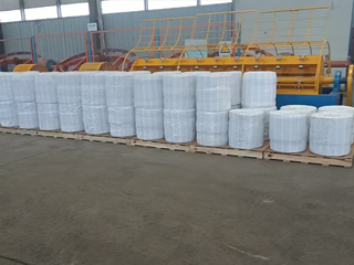
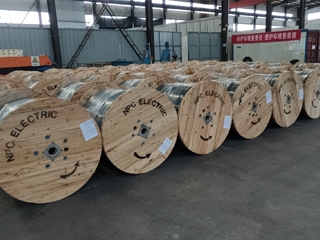
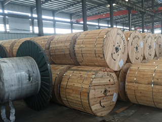
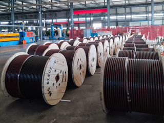
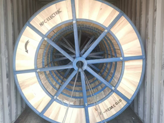
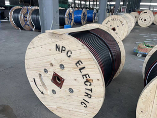
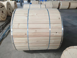
Product Packaging
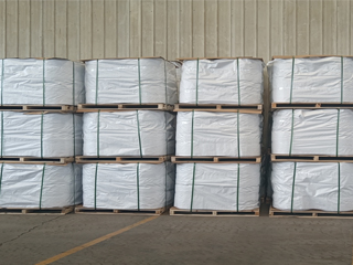
Wires and Cables packaging (1)
Wires and Cables packaging (2)
Wires and Cables packaging (3)
Wires and Cables packaging (4)
Wires and Cables packaging (5)
Wires and Cables packaging (6)
Wires and Cables packaging (7)
Wires and Cables packaging (8)
Related Products
AZUSA AAAC Conductor Cable
AZUSA AAAC (All Aluminum Alloy Conductor) cables comply with ASTM B399 standards and are characterized by high strength, excellent conductivity, and superior corrosion resistance. Meeting ASTM B398, B399, IEC 61089, and BS EN 50182 standards, this cable handles ampacity up to 900A at 75°C and voltages up to 33kV. The all-alloy construction avoids bimetallic corrosion, providing better resistance in harsh conditions than ACSR. Reduced weight minimizes sag and installation expenses, supporting longer spans. The Azusa AAAC Conductor Cable delivers low electrical losses, high mechanical endurance, and excellent weather tolerance. Flame-retardant variants available. Perfect for urban grids, renewable projects, and coastal setups, it provides cost-effective, low-maintenance power delivery in overhead applications globally, excelling in reliability and lifespan over conventional conductors.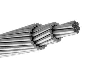
477 MCM PELICAN ACSR Conductor Cable
The ACSR CAA 477 MCM 18/1F PELICAN conductor is a high-performance Aluminium Conductor Steel Reinforced (ACSR) cable designed for use in overhead transmission and distribution line systems. Constructed with 18 strands of hard-drawn 1350-H19 aluminium helically stranded around a single galvanized steel wire, this conductor offers a well-balanced combination of electrical conductivity, lightweight design, and mechanical strength. Manufactured in compliance with ASTM B232, the PELICAN configuration is ideal for long-span installations where tensile strength, corrosion resistance, and current-carrying capability are critical. The galvanized steel core, available with Class A or B galvanization, provides excellent protection against environmental degradation while reinforcing the aluminium layers with the mechanical support required for demanding utility applications. Its 18/1 stranded design makes the PELICAN conductor particularly suitable for medium- and high-voltage overhead systems where both performance and cost-efficiency are important.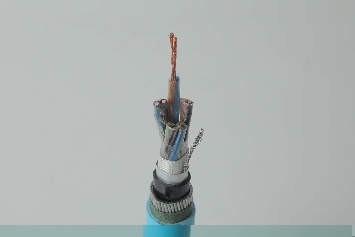
Instrumentation Cables—XLPE Insulated, Overall Screened, Lead Sheathed, Wire Armoured,PVC Sheathed Cables(CU/XLPE/OSCR/LEAD/SWA/PVC)
Instrumentation Cables with XLPE Insulated, Overall Screened, Lead Sheathed, Wire Armoured and PVC Sheathed construction (CU/XLPE/OSCR/LEAD/SWA/PVC) are designed for reliable signal and control transmission in harsh and corrosive environments. The copper conductor combined with XLPE insulation provides excellent electrical performance, thermal stability, and long service life. The overall screen effectively reduces electromagnetic interference, ensuring accurate signal transmission in complex industrial systems. A continuous lead sheath offers superior protection against moisture ingress, chemical attack, and hydrocarbon exposure. Steel wire armour enhances mechanical strength, making the cable suitable for demanding installation conditions. The outer PVC sheath provides additional environmental and mechanical protection. These instrumentation cables are widely used where durability, signal integrity, and environmental resistance are essential.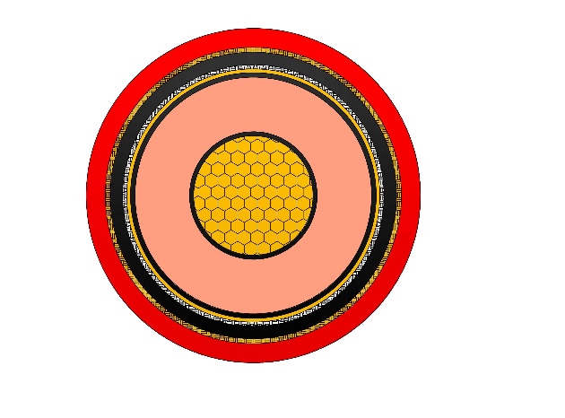
XAI Armoured Medium Voltage Power Cable(6/10kV, 12/20kV, 18/30kV)
NPC Electric XAI Armoured Medium Voltage Power Cable (6/10kV, 12/20kV, 18/30kV) delivers protected, high-performance medium voltage transmission. Constructed with copper or aluminium conductors, thermosetting XLPE insulation, metallic screen, bedding, galvanised steel wire armour (SWA), and tough outer sheath, it meets IEC 60502-2 requirements. The SWA layer offers outstanding resistance to mechanical damage, enabling direct burial without conduits. Low transmission losses, high current rating, and excellent overload tolerance ensure optimal efficiency. Optional LSZH sheath and water-blocking for added safety and reliability. Flame-retardant and environmentally robust, the XAI Armoured Medium Voltage Power Cable is widely selected for power grids, manufacturing plants, wind/solar farms, and infrastructure demanding reliable, maintenance-free medium voltage cabling with enhanced mechanical safeguarding in challenging terrains or high-impact zones worldwide.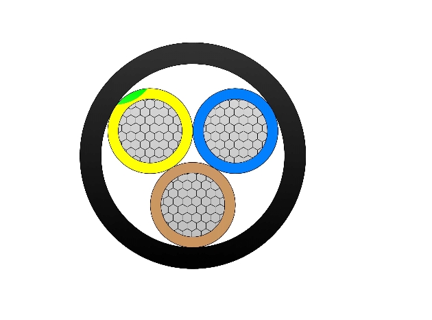
NA2XY 0.6/1 (1.2)kV Low Voltage Power Cable
NA2XY 0.6/1 (1.2)kV is a low-voltage power cable manufactured according to IEC 60502-1, suitable for fixed installation in indoor and outdoor environments, including underground and concrete installations where mechanical stress is minimal. This lightweight cable offers excellent electrical performance, high thermal stability, and superior resistance to moisture, chemicals, and mechanical stress. Suitable for direct burial, ducts, trays, or indoor fixed installations where no additional armour is required. With low dielectric losses and good current-carrying capacity, it minimizes energy waste. Flame-retardant and environmentally robust, the NA2XY 0.6/1 (1.2)kV Low Voltage Power Cable provides long service life and low maintenance costs. Widely used in industrial plants, commercial buildings, residential networks, and infrastructure projects needing reliable, cost-saving low-voltage aluminium cabling solutions worldwide.
FR-N30XA8E-R 18/30(36)kV Cable Gen to NF C 33-226 - Cu/XLPE/MDPE
The NF C 33-226 Cu-XLPE-MDPE 18/30(36)kV Triplex Cable is a high-performance three-core medium voltage power cable engineered for safe and reliable three-phase power transmission. Built with a Class 2 stranded copper conductor, cross-linked polyethylene (XLPE) insulation, and a medium-density polyethylene (MDPE) outer sheath, it offers exceptional electrical conductivity, insulation performance, and mechanical strength. Fully compliant with NF C 33-226, IEC 60502-2, and EN 60228 standards, this cable is ideal for industrial facilities, municipal grids, substations, and large commercial power systems. It ensures durability with superior water resistance (AD7), UV resistance (ISO 4892), and halogen-free (IEC/EN 60754-1) properties for enhanced safety and environmental protection. With a rated voltage of 18/30 (36)kV and a maximum conductor operating temperature of 90°C, the Cu-XLPE-MDPE Triplex cable provides efficient and stable power transmission in demanding medium- and high-voltage applications.FAQ From Customers
-
What are the advantages of power cables and overhead lines?(1) Reliable operation, because it is installed in a hidden place such as underground, it is less damaged by external forces, has less chance of failure, and the power supply is safe, and it will not cause harm to people; (2) The maintenance workload is small and frequent inspections are not required; (3) No need to erect towers; (4) Help improve power factor.
-
Which aspects should be considered when choosing the cross section of a power cable?(1) The long-term allowable working current of the cable; (2) Thermal stability once short circuited; (3) The voltage drop on the line cannot exceed the allowable working range.
-
What are the measures for cable fire prevention?(1) Use flame-retardant cables; (2) Use fireproof cable tray; (3) Use fireproof paint; (4) Fire partition walls and fire baffles are installed at cable tunnels, mezzanine exits, etc.; (5) Overhead cables should avoid oil pipelines and explosion-proof doors, otherwise local pipes or heat insulation and fire prevention measures should be taken.
-
What should be paid attention to during the transportation and handling of cables?(1) During transportation, loading and unloading, cables and cable reels should not be damaged. It is strictly forbidden to push the cable reels directly from the vehicle. Generally, cables should not be transported and stored flat. (2) Before transporting or rolling the cable reel, ensure that the cable reel is firm, the cable is wound tightly, the oil pipe between the oil-filled cable and the pressure oil tank should be fixed without damage, the pressure oil tank should be firm, and the pressure indication should meet the requirements.
-
What inspections should be carried out for the acceptance of cable lines?(1) The cable specifications should meet the regulations, the arrangement should be neat, no damage, and the signs should be complete, correct and clear; (2) The fixed bending radius of the cable, the related distance and the wiring of the metal sheath of the single-core power cable should meet the requirements; (3) The cable terminal and the middle head should not leak oil, and the installation should be firm. The oil pressure of the oil-filled cable and the meter setting should meet the requirements; (4) Good grounding; (5) The color of the cable terminal is correct, and the metal parts such as the bracket are completely painted; (6) There should be no debris in the cable trench, tunnel, and bridge, and the cover should be complete.
Welcome your inquiry
Honesty, Integrity, Frugality, Activeness and Passion