Understanding Transformer Cooling Systems: Oil-Cooled vs. Air-Cooled Solutions
2025-10-13
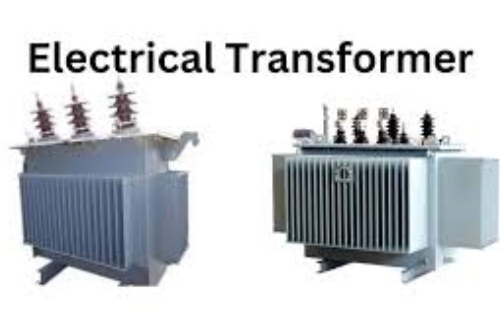
During operation, transformers generate significant heat in their cores and coils due to copper losses (I²R) and iron losses. To maintain transformer performance and prevent insulation breakdown, an effective transformer cooling system is required to ensure efficient voltage conversion and stable power distribution.
What is the Cooling System of a Transformer?
A transformer cooling system is designed to dissipate the heat generated during operation, keeping the winding temperature within safe limits. Without adequate cooling, overheating can shorten transformer life, degrade insulation, and increase the risk of failure.
The choice of cooling method depends on transformer type, rating, installation environment, and operational requirements. Common transformer cooling methods include:
- Natural Air (AN) – used in small dry-type transformers, where heat is dissipated directly into the surrounding air.
- Forced Air (AF) – fans provide additional airflow for larger dry-type units.
- Oil-Immersed Cooling – using mineral oil or synthetic ester as the cooling medium, suitable for medium to large power transformers.
- Water-Cooled Systems – applied in high-capacity units where oil-to-water heat exchangers are required.
Transformer Cooling Classes
Transformers are categorized into cooling classes defined by IEC and IEEE standards. Each designation specifies how heat is transferred from windings to the environment.
- AN / AF (Air Natural / Air Forced): Used for dry-type transformers. Cooling relies on natural or forced air circulation.
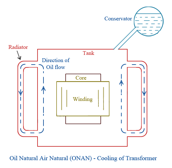
- ONAN (Oil Natural Air Natural): Transformer oil circulates naturally, and heat is dissipated into the surrounding air.
- ONAF (Oil Natural Air Forced): Oil circulation remains natural, but fans force air over radiators.
- OFAF (Oil Forced Air Forced): Oil is pumped through radiators while fans accelerate air cooling.
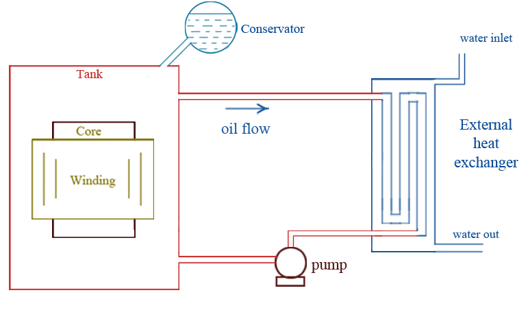
- ODAF / OFWF (Oil Directed Air Forced / Oil Forced Water Forced): Advanced cooling for very large power transformers, combining forced oil flow with air or water cooling.
|
Cooling Method |
Cooling Medium |
Circulation Type |
Typical Application |
Advantages |
Limitations |
|
Air Natural (AN) |
Air |
Natural convection |
Small dry-type transformers |
Simple, maintenance-free, safe |
Limited capacity, less efficient |
|
Air Forced (AF) |
Air |
Fans (forced air flow) |
Medium dry type transformers |
Better cooling than AN, compact |
Requires fans and maintenance |
|
Oil Natural Air Natural (ONAN) |
Mineral oil + Air |
Natural oil flow, natural air convection |
Distribution transformers up to 20–30 MVA |
Reliable, widely used, self-regulated |
Cooling capacity is limited for larger units |
|
Oil Natural Air Forced (ONAF) |
Mineral oil + Air |
Natural oil flow, forced air with fans |
Medium power transformers (30–100 MVA) |
Increased load capacity, flexible |
Requires a fan system, higher O&M cost |
|
Oil Forced Air Forced (OFAF) |
Mineral oil + Air |
Oil pumps + fans |
Large power transformers |
High cooling efficiency, supports overload |
Complex system, more maintenance |
|
Oil Directed Air Forced (ODAF) |
Mineral oil + Air |
Directed oil flow + fans |
Extra-large transformers |
Ensures uniform cooling of windings |
Higher cost, complex design |
|
Oil Forced Water Forced (OFWF) |
Mineral oil + Water |
Oil pumps + water circulation |
Very large transformers in power plants |
Very high cooling capacity, compact |
Requires continuous water supply, corrosion risk |
These classifications balance efficiency, cost, and reliability depending on transformer rating and site conditions.
Transformer Oil Cooling System
In an oil-immersed transformer, the windings and core are submerged in insulating oil. The oil acts as both an insulator and a cooling medium.
Working Principle
- Heat generated in the core and coils is transferred to the oil.
- Hot oil rises and circulates naturally or with pumps.
- Heat is released to the environment through radiators or heat exchangers.
Advantages
- High cooling efficiency, suitable for large power transformers.
- Oil improves dielectric strength, extending transformer life.
- Flexible: can integrate natural air, forced air, or water-cooled systems.
Limitations
- Requires periodic oil testing and maintenance.
- Risk of leakage or fire if not properly managed.
Transformer Air Cooling System
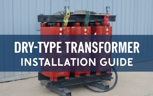
Dry type transformers use air cooling as the primary method. Cooling is achieved by direct heat transfer from windings to the surrounding air.
Types of Air Cooling
- Natural Air Cooling (AN): Relies on natural convection; simple and maintenance-free.
- Forced Air Cooling (AF): Fans blow air across windings to enhance cooling.
Advantages
- No oil, reducing fire risk and environmental concerns.
- Lower maintenance compared to oil-filled units.
- Suitable for indoor, commercial, or environmentally sensitive installations.
Limitations
- Less efficient than oil cooling for high-capacity transformers.
- Sensitive to dust and humidity in industrial environments.
Water-Cooled Transformer Cooling System
For very large transformers, water-cooled systems are used. Heat is transferred from oil to water through heat exchangers.
- Advantages: High cooling capacity, compact design, effective in hot climates.
- Disadvantages: Requires a reliable water supply and strict maintenance to prevent corrosion and leakage.
Choosing the Right Transformer Cooling Method
When selecting a transformer cooling system, engineers must consider:
- Transformer rating: Larger units typically require oil cooling or forced cooling methods.
- Installation site: Indoor installations may prefer dry-type transformers with air cooling.
- Safety and environment: Oil-cooled units require fire protection and monitoring; air-cooled or water-cooled units may be safer in certain environments.
- Operational efficiency: Forced cooling systems (fans, pumps) improve load capacity but increase operational costs.
Practical Applications
- Distribution Transformers (≤2500 kVA): Often use oil natural air natural (ONAN) or dry type with natural air cooling.
- Medium Power Transformers (10–100 MVA): Commonly adopt ONAF or OFAF for improved load handling.
- Large Power Transformers (>100 MVA): Require forced oil systems combined with air or water cooling for continuous reliability.
The cooling system of a transformer plays a critical role in maintaining efficiency, extending service life, and ensuring safe operation. Both oil-cooled and air-cooled transformer systems have unique advantages:
- Transformer oil cooling systems dominate in high-capacity and outdoor power applications.
- Transformer air cooling systems excel in indoor, environmentally sensitive, and safety-critical locations.
Understanding different transformer cooling classes and cooling methods enables engineers to make informed choices for reliable and efficient power infrastructure.
Related Articles

Related Products
NYRY 0.6/1kV Low Voltage Power Cable
NYRY 0.6/1kV are low voltage power cables designed according to BS 5467 standard, suitable for fixed installation in indoor, outdoor, underground, cable ducts or concrete (not subject to vibration) environments, with steel wire armouring for mechanical protection. The cable features stranded copper conductors insulated with high-quality PVC, ensuring dependable electrical performance and thermal resistance under normal operating conditions. The metallic concentric conductor layer provides effective grounding and enhanced fault current capability, while the robust PVC outer sheath offers protection against moisture, abrasion, and external mechanical stress. Rated at 0.6/1kV and manufactured in accordance with relevant IEC standards, the NYRY cable is suitable for fixed installation both indoors and outdoors. Its construction supports long service life, consistent power delivery, and safe operation in demanding environments.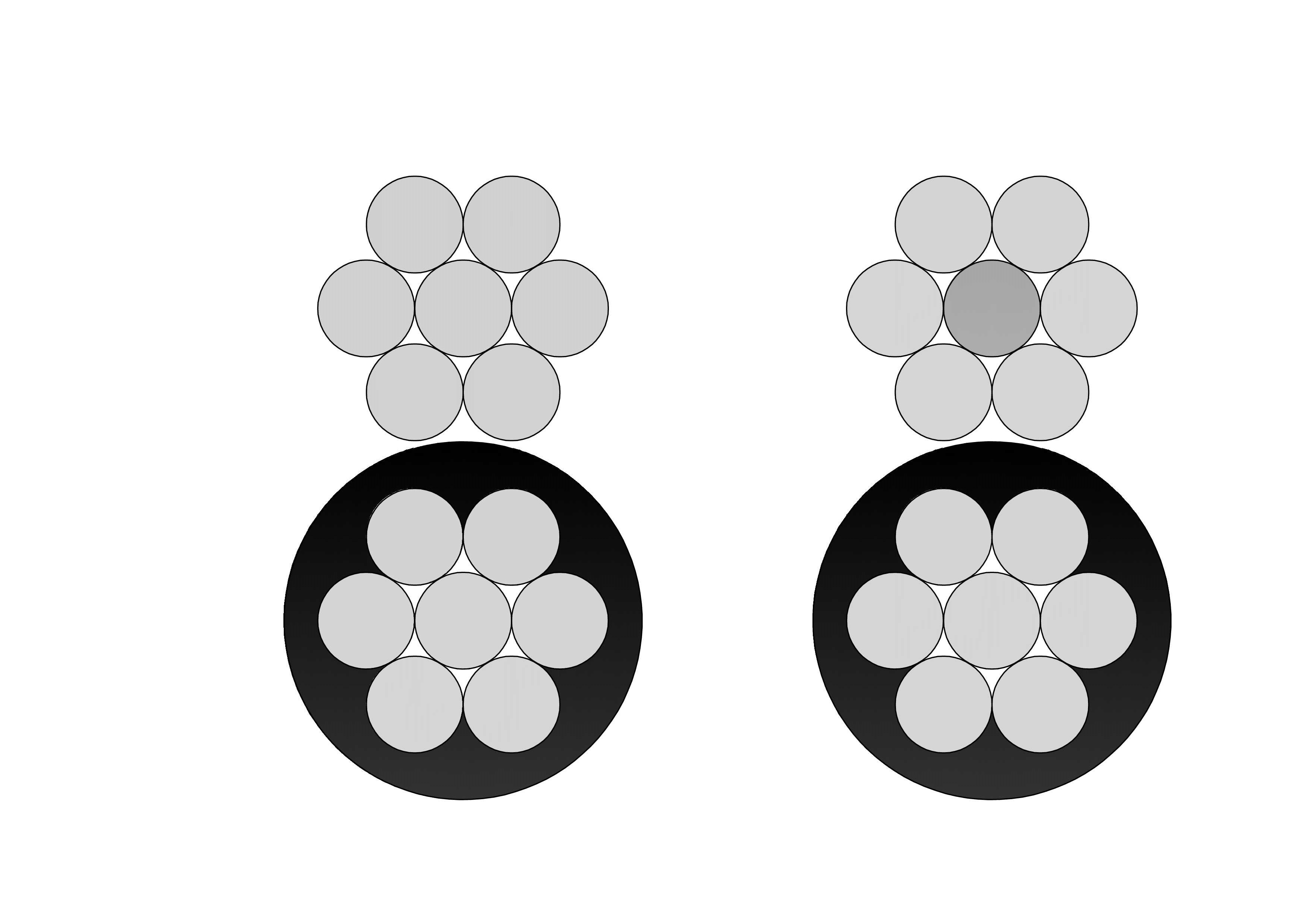
2 Schnauzer Aluminum Conductor Duplex Overhead Service Drop Cable
2 Schnauzer Aluminum Conductor Duplex Overhead Service Drop Cable is designed for reliable secondary overhead power delivery from utility distribution lines to residential and light commercial service entrances. The duplex construction consists of two concentrically stranded aluminum conductors, commonly used as a phase conductor and a neutral messenger, providing both electrical transmission and mechanical support. The No. 2 Schnauzer conductor size offers a practical balance between current-carrying capacity and tensile strength, ensuring controlled sag for short- to medium-span service drop installations. Aluminum conductors provide lightweight handling, excellent corrosion resistance, and simplified installation in outdoor environments. Manufactured in accordance with ASTM standards and utility specifications, the 2 Schnauzer Aluminum Conductor Duplex Overhead Service Drop Cable delivers uniform stranding, stable conductivity, and dependable long-term performance. It is widely selected by utilities and contractors seeking a durable, cost-effective solution for overhead service drop applications.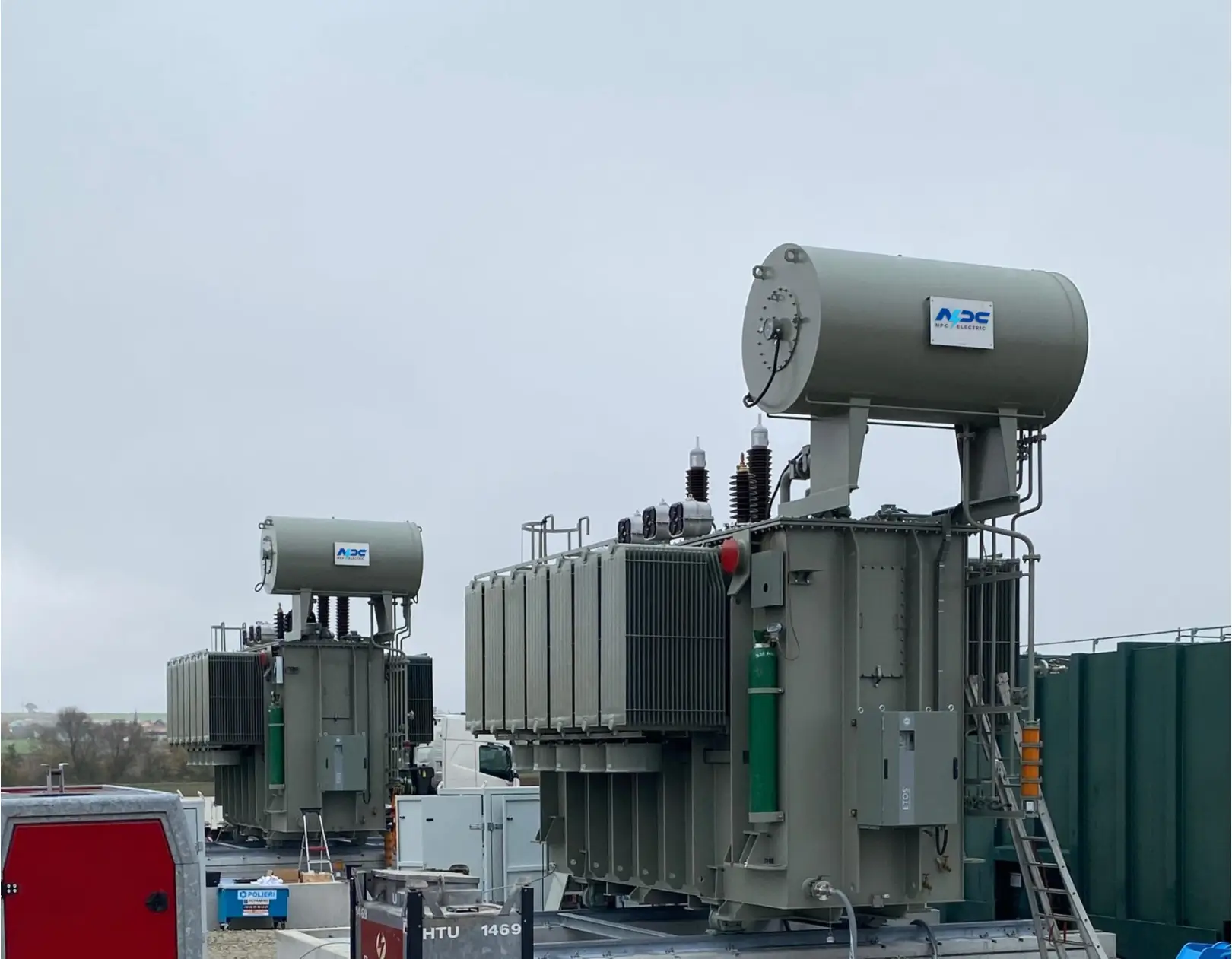
330kV 3-Phase 2-Winding Power Transformer
NPC Electric 330kV 3-Phase 2-Winding Power Transformer is a cornerstone of Extra-High Voltage (EHV) power systems, engineered to provide seamless voltage regulation and long-term operational reliability. Designed for heavy-duty utility and industrial applications, this transformer features a high-permeability core made of premium cold-rolled grain-oriented (CRGO) silicon steel, which significantly reduces no-load losses and acoustic noise levels. The dual-winding architecture is structurally reinforced to withstand extreme electromagnetic forces and mechanical stresses during grid short-circuit events. Safety and longevity are prioritized through an advanced insulation system, utilizing high-grade cellulose pressboard and inhibited mineral oil. This is complemented by precision-calculated electrostatic shielding to suppress partial discharge (PD) effectively. The transformer tank is a robust, fully-welded structure designed to maintain a full vacuum, ensuring hermetic sealing against environmental contaminants.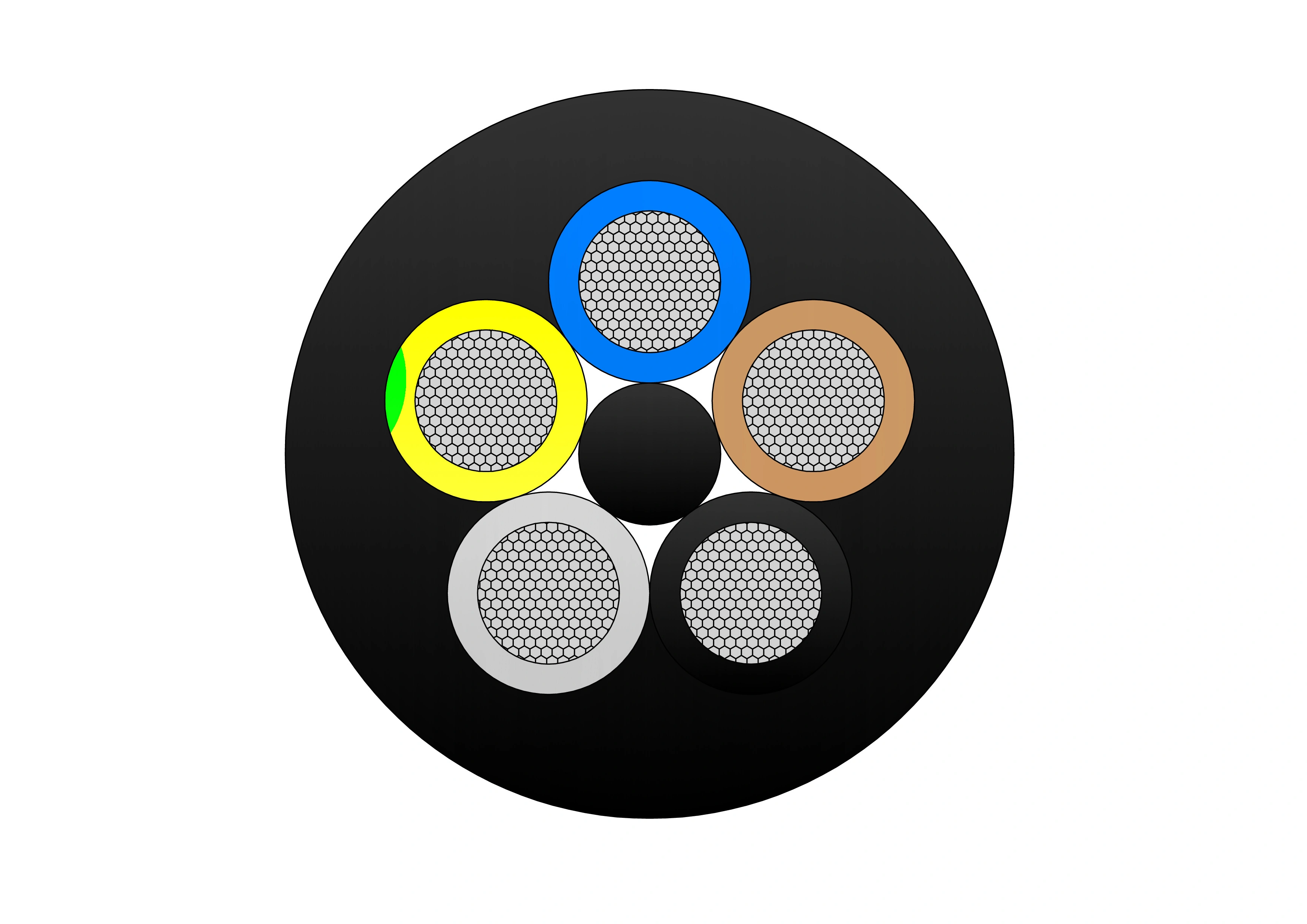
(N)TSCGECEWOU - 3.6/6kV, 6/10kV, 8.7/15kV and 12/20kV Submersible Cable
The (N)TSCGECEWOU - 3.6/6kV, 6/10kV, 8.7/15kV, and 12/20kV Submersible Cable is a flexible, heavy-duty medium-voltage cable designed for submersible applications in mining, tunneling, and industrial water environments. It features class 5 finely stranded tinned copper conductors for flexibility and corrosion resistance, semi-conductive conductor and insulation screens, EPR (ethylene propylene rubber) insulation for superior dielectric strength and 90°C continuous rating, copper braid screen for EMI protection and grounding, control/monitoring conductors, and a watertight, abrasion-resistant rubber outer sheath (e.g., 5GM5 type) that prevents water ingress up to high pressures (e.g., 50 bar). Compliant with DIN VDE 0250 and relevant IEC standards, it offers high mechanical strength, longitudinal water blocking, and resistance to oils, chemicals, and flames. Suitable for submersible pumps, dredgers, and underwater equipment, the (N)TSCGECEWOU Submersible ensures reliable power transmission in submerged conditions with minimal maintenance.
15KV Oil Immersed Substation Transformer
NPC ELECTRIC's 15kV Oil Immersed Substation Transformer is designed for medium-voltage substations that require dependable power transformation, high insulation reliability, and long-term operational stability. By adopting a mature oil-immersed insulation system, the transformer ensures excellent dielectric performance. This 15kV oil immersed substation transformer features a sealed tank structure that effectively protects internal components from moisture, dust, and external contamination. With low noise operation and reliable voltage regulation performance, the transformer is well suited for modern substations serving industrial, commercial, and infrastructure power distribution networks.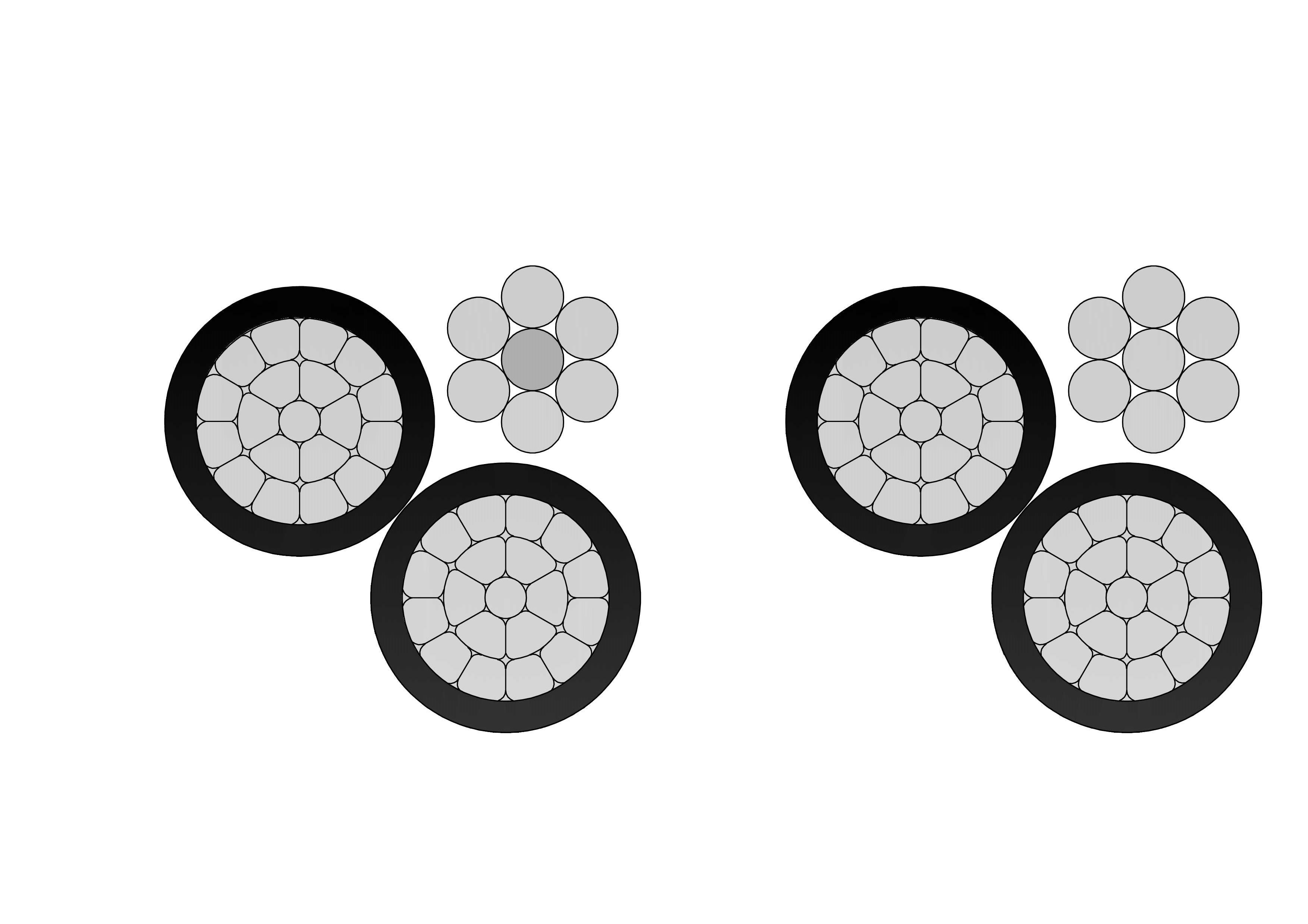
2/0 Trophon Aluminum Conductor Triplex Overhead Service Drop Cable
The 2/0 Trophon Aluminum Conductor Triplex Overhead Service Drop Cable delivers superior performance for overhead power distribution. Engineered with high-quality 1350-H19 aluminum conductors, black cross-linked polyethylene (XLPE) insulation, and a bare ACSR neutral messenger, this triplex cable ensures excellent conductivity, weather resistance, and mechanical strength. Rated for 600V phase-to-phase at up to 90°C conductor temperature (XLP), it offers approx. 230A ampacity, making it ideal for residential and light commercial service entrances. Compliant with ASTM B-230, B-231, B-232, and ICEA S-76-474 standards, the cable withstands harsh outdoor conditions while maintaining flexibility and reliability.
4 Barnacles Aluminum Conductor Triplex Overhead Service Drop Cable
The 4 Barnacles Aluminum Conductor Triplex Overhead Service Drop Cable is designed for reliable overhead electrical service connections in residential and light commercial utility distribution systems. The cable structure includes two insulated aluminum phase conductors twisted around a bare aluminum neutral messenger, providing stable electrical transmission and dependable mechanical support. Manufactured using high-quality aluminum and durable weather-resistant insulation compounds, the 4 Barnacles Aluminum Conductor Triplex Overhead Service Drop Cable offers low electrical resistance, strong corrosion resistance, and long service life in outdoor environments. Its optimized conductor construction allows efficient installation while maintaining adequate tensile strength for aerial applications. The cable is engineered to perform reliably under UV exposure, wind loading, and temperature variation. Comprehensive quality management systems and standardized testing procedures are implemented throughout production to ensure compliance with utility and industry standards and to deliver consistent, dependable performance in service.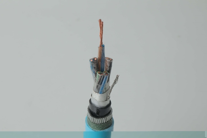
Instrumentation Cables—XLPE Insulated, Overall Screened, DRYLAM Layered, Wire Armoured PVC Sheathed Cables(CU/XLPE/OSCR/DRYLAM/SWA/PVC)
CU/XLPE/OSCR/DRYLAM/SWA/PVC instrumentation cables are engineered to deliver stable signal transmission under harsh environmental and mechanical conditions. XLPE insulated copper conductors provide excellent dielectric performance and resistance to thermal aging. The overall screen minimizes electromagnetic interference, ensuring precise signal transmission in sensitive instrumentation circuits. The DRYLAM water-blocking layer offers effective protection against moisture ingress, enhancing cable reliability in humid or buried installations. Steel wire armour improves resistance to mechanical stress and external damage, while the PVC sheath protects against abrasion, oils, and chemicals. This balanced construction combines electrical performance, water resistance, and mechanical durability for long-term industrial use.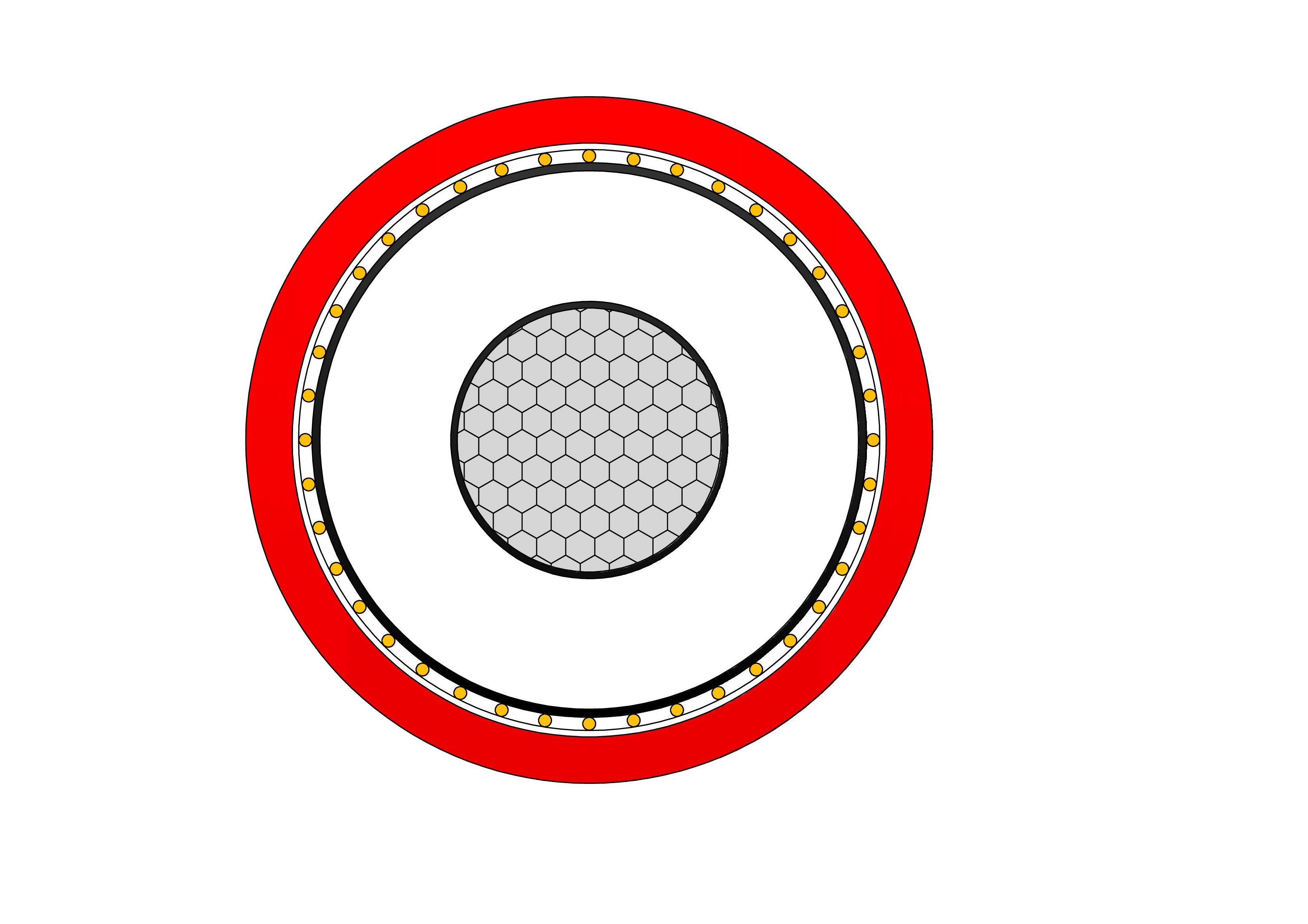
NA2XSY Medium Voltage Power Cable(6/10kV, 12/20kV, 18/30kV)
NA2XSY are medium voltage power cables with aluminum conductors and XLPE insulation, designed according to IEC 60502-2 standards. Constructed with aluminium conductors, thermosetting XLPE insulation, metallic screen (copper tape or wires), and tough PVC outer sheath, it meets IEC 60502-2 requirements. The screen ensures electromagnetic compatibility and fault protection. Low tan delta, high breakdown strength, and excellent thermal endurance minimize losses and support overloads. PVC sheath provides reliable mechanical and moisture protection for fixed installations. Optional longitudinal water-blocking improves performance in damp areas. Flame-retardant and easy to install, the NA2XSY Medium Voltage Power Cable is favored for power grids, manufacturing plants, commercial developments, and renewable energy sites demanding cost-efficient single-core medium voltage cabling with proven durability and performance in buried or tray installations worldwide.
Type 260 Armoured Mining Cable with Pilot Core
The Type 260 Armoured Mining Cable with Pilot Core is a medium-voltage, rubber-insulated cable designed for heavy-duty mining applications requiring high mechanical strength and electrical reliability. It features flexible stranded tinned copper conductors, EPR insulation, and tinned copper braiding for excellent screening. The pliable galvanised steel wire armour (SWA) provides superior mechanical protection, making it suitable for harsh mining environments. The interstitial pilot core allows enhanced control and monitoring functions. With a PCP heavy-duty sheath, it offers flame retardancy, oil resistance, and durability. Compliant with AS/NZS 1802 and related standards, it is ideal for feeder cables, mining machinery power supply, and transportable substations. The Type 245 is ideal for high-power trailing in coal and metalliferous mines, powering longwall shearers, continuous miners, face conveyors, and critical equipment with enhanced safety via pilot core and armour.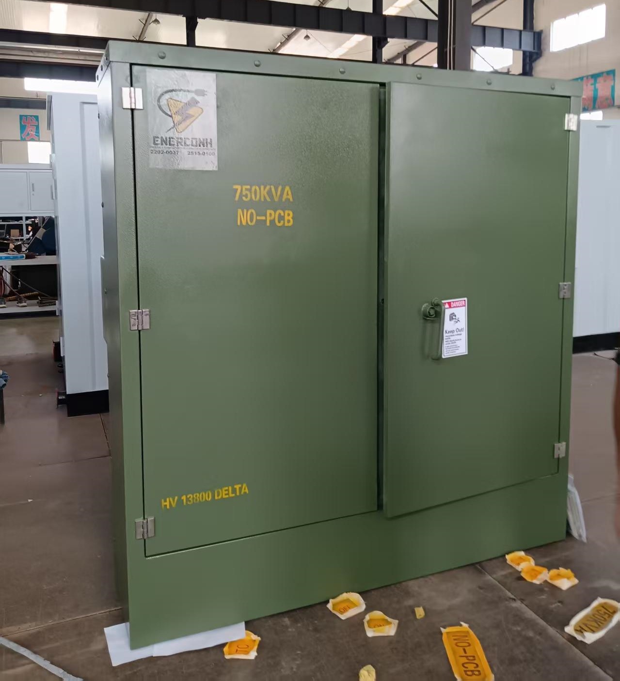
750kVA Radial Feed Pad Mounted transformer To Honduras
The 750kVA Radial Feed Pad Mounted Transformer is a high-capacity, three-phase, oil-immersed distribution transformer specifically configured for radial feed (single-source primary supply) applications. It is ideal for utility substations, commercial complexes, industrial sites, and large residential developments requiring dependable step-down from medium-voltage primary lines to low-voltage secondary service. Fully compliant with ANSI C57.12.00, IEEE C57.12.90, IEEE C57.12.34 (for pad-mounted compartmental-type transformers), IEC 60076, and DOE 2016 efficiency standards (aligned with 2029 amendments for reduced losses), this 750 kVA unit provides excellent energy efficiency (>99.2% typical), low no-load/load losses, robust overload capability, and long-term reliability in outdoor environments. Typical specifications include mineral oil or FR3 natural ester fluid (ONAN cooling), aluminum or copper windings, primary voltage 13.8kV (13800V Delta or 12470GrdY/7200 common for Latin America/Honduras compatibility), secondary 480Y/277V (or 208Y/120V, custom options), BIL 95kV HV / 30kV LV, impedance 5.75–7.0% (±7.5%), ±2×2.5% taps, radial-feed dead-front design with three high-voltage bushings (H1, H2, H3), bayonet fuses + partial-range current-limiting fuses, load-break switch (optional), lightning arresters, pressure relief valve, oil level/temperature gauges, and ANSI 70 gray (or Munsell green) finish. Low sound level (<60 dB), strong short-circuit withstand, and radial-feed configuration suit single-source underground or overhead feeds.
NTSCGEWOU 3.6/6kV, 6/10kV, 8.7/15kV, 12/20kV Cable
The NTSCGEWOU 3.6/6kV, 6/10kV, 8.7/15kV, 12/20kV Cable is a high-performance flexible medium-voltage trailing/reeling cable engineered for extreme mining and tunneling conditions. It comprises class 5 finely stranded tinned copper phase conductors for superior flexibility and corrosion resistance, semi-conductive conductor and insulation screens for field control, EPR insulation for excellent dielectric strength and 90°C continuous operation, copper wire braid screen for EMI protection and grounding, control conductors, monitoring conductor (ÜL), and a durable rubber outer sheath resistant to oil, flame, abrasion, tearing, and mechanical stress. Compliant with DIN VDE 0250, it handles high tensile loads, fast reeling speeds, tight bending radii, and effective EMC shielding across all voltage levels. The NTSCGEWOU delivers safe, reliable MV power to mobile equipment such as shearers, tunnel boring machines, draglines, and conveyors in harsh underground and opencast environments, minimizing downtime and ensuring long-term operational efficiency.
Step Up Dry Type Transformer Copper Winding High Overload Capacity
The Step Up Dry Type Transformer Copper Winding High Overload Capacity is a robust, oil-free power solution designed to increase (step up) voltage from lower primary levels to higher secondary outputs for efficient power transmission in indoor applications. This three-phase cast resin dry type transformer features premium high-conductivity copper windings fully encapsulated in epoxy resin under vacuum pressure, paired with low-loss grain-oriented silicon steel cores to achieve superior energy efficiency (typically 98%+), minimal no-load and load losses, and excellent partial discharge performance (<10pC). Compliant with IEC 60076-11, IEEE/ANSI, and relevant efficiency standards, this transformer commonly steps up voltages such as 0.4kV/480V primary to 6.6kV, 11kV, 13.8kV, 22kV, or 35kV secondary (Dyn11 or custom vector group), with capacities from 100kVA to several MVA, making it ideal for renewable energy systems, generator step-up, industrial processes, and utility indoor substations prioritizing safety, sustainability, and overload resilience.
(N)TSCGEWOU 3.6/6kV, 6/10kV, 8.7/15kV and 12/20kV ATB Cable
The (N)TSCGEWOU 3.6/6kV, 6/10kV, 8.7/15kV, and 12/20kV ATB Cable is a medium voltage flexible power cable designed in compliance with VDE 0250 standards. It features Class 5 tinned copper conductors, EPR rubber insulation, semi-conductive layers, halogen-free flame-retardant rubber sheath, and an earth detection conductor. The ATB construction ensures superior mechanical strength, oil resistance, abrasion resistance, and flame retardancy, making it ideal for open-pit mining, tunneling, and other heavy-duty mobile equipment applications under extreme mechanical stress. It includes tinned class 5 copper phase conductors, semi-conductive screens, EPR insulation for reliable dielectric and thermal performance (90°C rating), copper braid screen, control conductors, monitoring conductor (ÜL), anti-torsion braid to reduce twisting under load, and a robust rubber sheath resistant to oils, flames, abrasion, and mechanical damage.
1/0 Gammarus Aluminum Conductor Triplex Overhead Service Drop Cable
NPC Electric 1/0 Gammarus Triplex Service Drop Cable provides reliable overhead secondary distribution for residential applications. Consisting of two 1/0 AWG aluminum phase conductors and one neutral messenger (7-strand) insulated with cross-linked polyethylene (XLPE) and twisted in triplex form, it meets ASTM, ICEA, and international standards. The robust insulation resists sunlight, moisture, and mechanical damage for decades of outdoor service. Lightweight design simplifies installation with low sag and easy handling. The 1/0 Gammarus Triplex Service Drop Cable ensures minimal losses, high current capacity, and excellent weather performance up to 600V. Self-supporting messenger reduces pole loading. Flame-retardant options enhance safety. Commonly chosen for two-phase power delivery with neutral in subdivisions, rural homes, and temporary connections requiring safe, economical aerial bundled solutions with proven durability.Welcome your inquiry
Honesty, Integrity, Frugality, Activeness and Passion