A Complete Guide to Current Transformers for Accurate Power Monitoring
2025-11-07
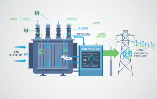
In modern electrical systems, accurate measurement of current is essential for power monitoring, energy management, and system protection. Directly measuring high current flowing through power lines is both unsafe and impractical. To address this, engineers use a current transformer (CT)—a specialized instrument that scales down large currents to measurable levels for meters and protective relays.
Current transformers are fundamental components of every power distribution, industrial automation, and energy monitoring system, ensuring both safety and accuracy.
1. What Is a Current Transformer?
A current transformer is an instrument transformer that converts a primary current (often hundreds or thousands of amperes) into a proportional, smaller secondary current—typically 1A or 5A—for measurement and protection purposes.
By magnetically coupling its primary and secondary windings around a magnetic core, the CT isolates the measuring circuit from the high-voltage system while maintaining proportionality between the primary and secondary currents.
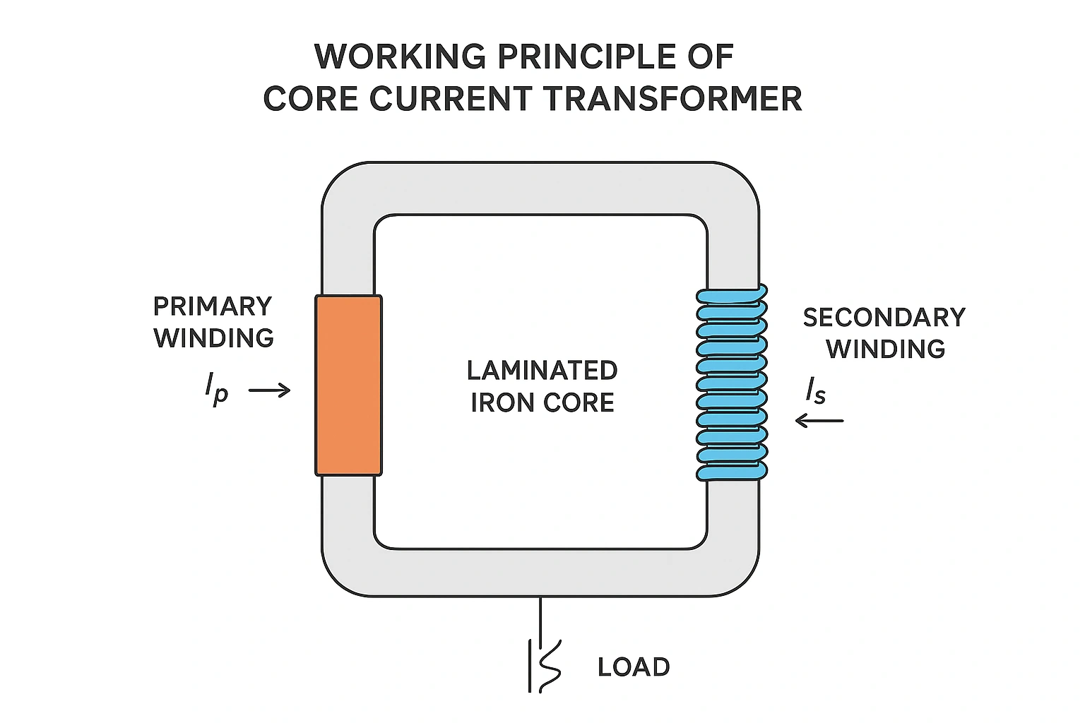
2. Working Principle of Current Transformers
The working principle of a current transformer is based on electromagnetic induction.
When alternating current flows through the primary conductor, it generates a magnetic flux in the core of the current transformer. This magnetic field induces a current in the secondary winding according to the turns ratio:
Ip/Is=Ns/NpI_p / I_s = N_s / N_pIp/Is=Ns/Np
where:
- Iₚ = Primary current
- Iₛ = Secondary current
- Nₚ = Primary turns
- Nₛ = Secondary turns
For example, a CT with a ratio of 1000:5 reduces a 1000A primary current to 5A at the secondary terminal. This enables standard metering devices to safely measure current without direct contact with high voltage.
3. Construction of a Current Transformer
A core current transformer consists of three main components:
- Magnetic Core – Made of laminated silicon steel or nanocrystalline material, the core provides a low-loss path for magnetic flux. Its design directly affects accuracy and saturation behavior.
- Primary Winding – Usually consists of one or a few turns of heavy conductor connected in series with the load circuit.
- Secondary Winding – Composed of many turns of fine copper wire, delivering a reduced current proportional to the primary.
Additional components may include insulation, a terminal block, and a protective case made of epoxy resin or thermoplastic for mechanical strength and electrical safety.
4. Types of Current Transformers
a. Wound Current Transformer
Both the primary and secondary windings are wound on the magnetic core. These CTs offer high accuracy and are used in precision metering and low-current applications.
b. Bar-Type Current Transformer
The primary winding is a solid conductor (busbar or cable) passing through the CT core. It is commonly used in switchgear and substation installations.
c. Toroidal Current Transformer
Also known as a core current transformer, it has no primary winding. The power cable itself passes through the CT’s circular core. This type is widely used in panel metering and leakage detection systems.
d. Split-Core Current Transformer
This CT can be opened and clamped around an existing conductor, allowing installation without disconnecting cables—ideal for retrofit power monitoring and maintenance.
5. Current Transformer Connection Methods
Proper current transformer connection ensures accurate measurement and safety. CTs can be connected in several configurations depending on the system design:
- Single CT Connection: For single-phase circuits or neutral current measurement.
- Two-CT Connection: Common in delta-connected systems for line-to-line current measurement.
- Three-CT Connection: Used in three-phase systems for full current monitoring and protection.
When multiple CTs are connected to measuring devices or protective relays, attention must be paid to polarity markings (P1–P2, S1–S2) to maintain correct phase relationships.
6. Accuracy and Burden in Current Transformers
The performance of a current transformer depends on two key parameters: accuracy class and burden.
- Accuracy Class: Defines the allowable error in the current ratio and phase angle. Standard classes include 0.2, 0.5, 1, and 3 for metering CTs, and 5P or 10P for protection CTs.
- Burden: The load impedance connected to the CT secondary circuit (e.g., meters, relays). Excessive burden can cause ratio errors or saturation of the core, reducing accuracy.
Maintaining rated burden and correct installation ensures reliable readings and protects downstream devices.
7. Applications of Current Transformers
Current transformers are used wherever precise current measurement or isolation is required. Key applications include:
a. Power Monitoring and Metering
Used in smart grids, industrial automation, and building energy management systems (BEMS) to measure consumption and load balance.
b. Protection Systems
CTs supply input signals to protective relays, enabling fault detection, differential protection, and overcurrent protection in switchgear.
c. Instrumentation and Control
Used in panel meters, SCADA systems, and PLC-based monitoring for process control and system analysis.
d. Renewable Energy and Distributed Generation
Current transformers monitor current flow in solar farms, wind turbines, and battery energy storage systems, ensuring proper synchronization and grid stability.
8. Engineering Considerations for CT Selection
When designing or selecting a current transformer, engineers must evaluate several factors:
- Primary current rating and system voltage
- Accuracy class based on metering or protection purpose
- Core material and saturation characteristics
- Installation environment (indoor, outdoor, high temperature, humidity)
- Mechanical form (bar, wound, toroidal, split-core)
- Safety standards such as IEC 61869-2 or ANSI C57.13
Choosing the right CT ensures long-term stability, safety, and compliance with international regulations.
9. Maintenance and Safety
Proper maintenance of current transformers is critical to prevent measurement errors or equipment damage:
- Periodically inspect terminals and secondary wiring.
- Ensure the secondary circuit is never open-circuited under load, as this may generate dangerous voltages.
- Verify polarity and burden during commissioning.
- Test insulation resistance and ratio accuracy at regular intervals.
Adhering to best practices guarantees the longevity and reliability of CTs in demanding electrical environments.
10. The Future of Current Transformers
Advancements in digital CTs and optical current sensors are reshaping traditional measurement methods.
- Electronic CTs integrate signal conditioning and communication modules for smart grid compatibility.
- Fiber-optic current transformers (FOCTs) provide high accuracy and immunity to electromagnetic interference.
These emerging technologies expand the role of CTs from passive devices to intelligent nodes in modern power monitoring networks.
The current transformer remains a cornerstone of electrical engineering—essential for accurate measurement, control, and protection. From conventional core current transformers to digital CTs integrated into smart substations, their role continues to evolve alongside the global transition toward smarter, safer, and more efficient energy systems.
Understanding the current transformer connection, design, and working principle is vital for engineers who seek to optimize performance, ensure system reliability, and maintain precise power monitoring across modern electrical networks.
Related Articles


Related Products
NA2XRY 0.6/1kV Low Voltage Power Cable
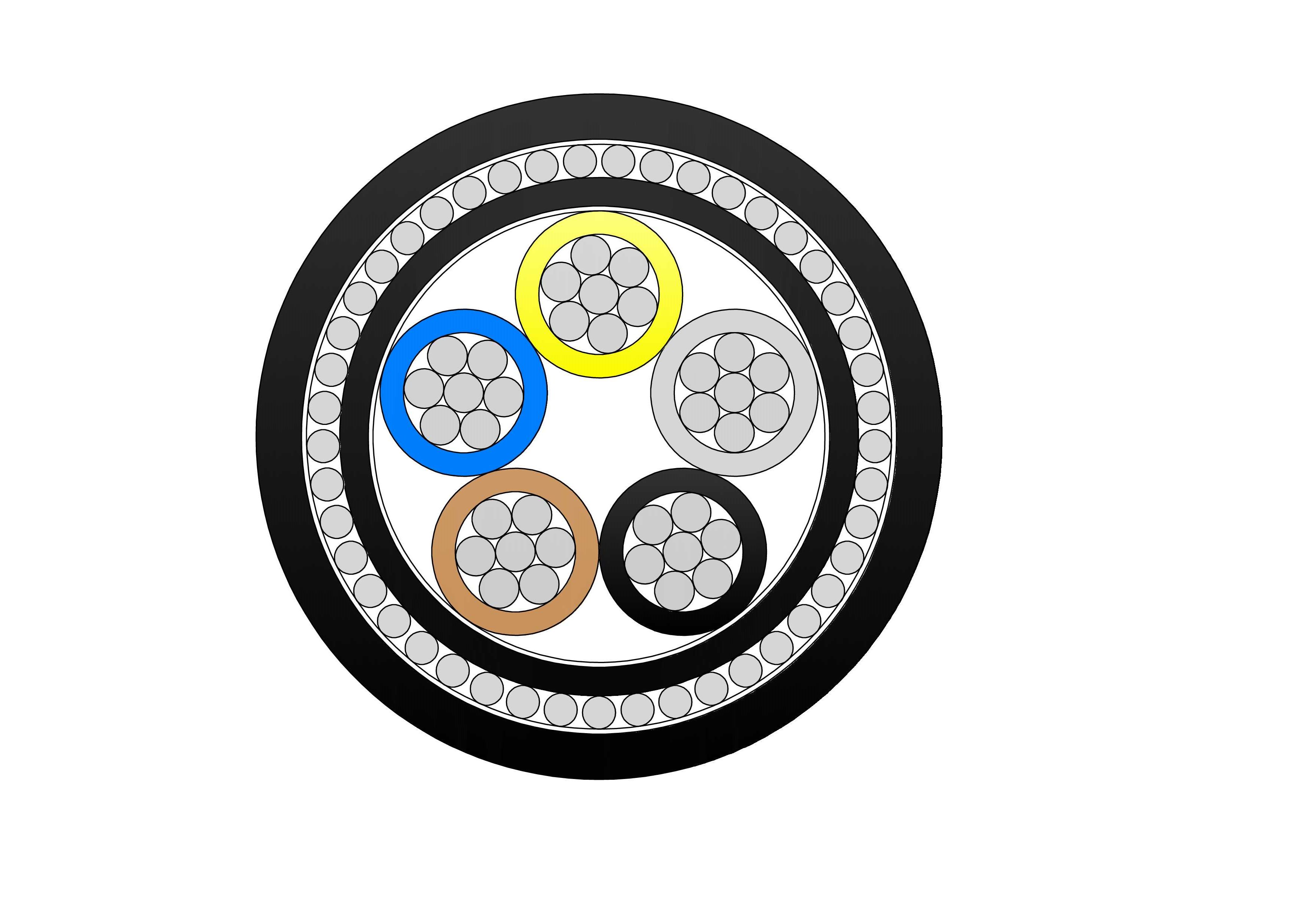
NA2XRY 0.6/1kV are low voltage power cables designed according to BS 5467 standard, suitable for fixed installation in indoor, outdoor, underground, or concrete (Can withstand certain mechanical forces) environments. Constructed with aluminium conductors, thermosetting XLPE insulation, PVC inner bedding, double galvanised steel tape armour, and tough PVC outer sheath, it meets IEC 60502-1 requirements. The STA armour offers outstanding resistance to compression and external forces, enabling direct burial. Lightweight aluminium lowers installation costs while ensuring good current rating and low losses. Flame-retardant and stable in harsh conditions, the NA2XRY 0.6/1kV Low Voltage Power Cable is favoured for manufacturing plants, renewable sites, commercial complexes, and infrastructure demanding reliable, low-maintenance low-voltage cabling with enhanced mechanical safeguarding.2Y-high-voltage-power-cable-2.webp)
A2XS(FL)2Y HDPE High Voltage 76/132 (145)kV Power Cable
The A2XS(FL)2Y HDPE High Voltage 76/132 (145) kV Power Cable is a single-core aluminum conductor cable with XLPE insulation and HDPE sheath, engineered for high-voltage power transmission in demanding industrial and utility applications. Built to IEC 60840 standards, it offers superior electrical performance, mechanical strength, and environmental resistance. Suitable for underground, underwater, outdoor, indoor, and duct installation, it features water-blocking tape to prevent internal water propagation, ensuring long-term reliability in power stations, industrial facilities, and distribution networks. The A2XS(FL)2Y HDPE is widely used in major UHV transmission grids, underground/submarine lines, river crossings, offshore wind connections, and large-scale renewable energy projects where water ingress protection, efficiency, and ultra-reliability are essential.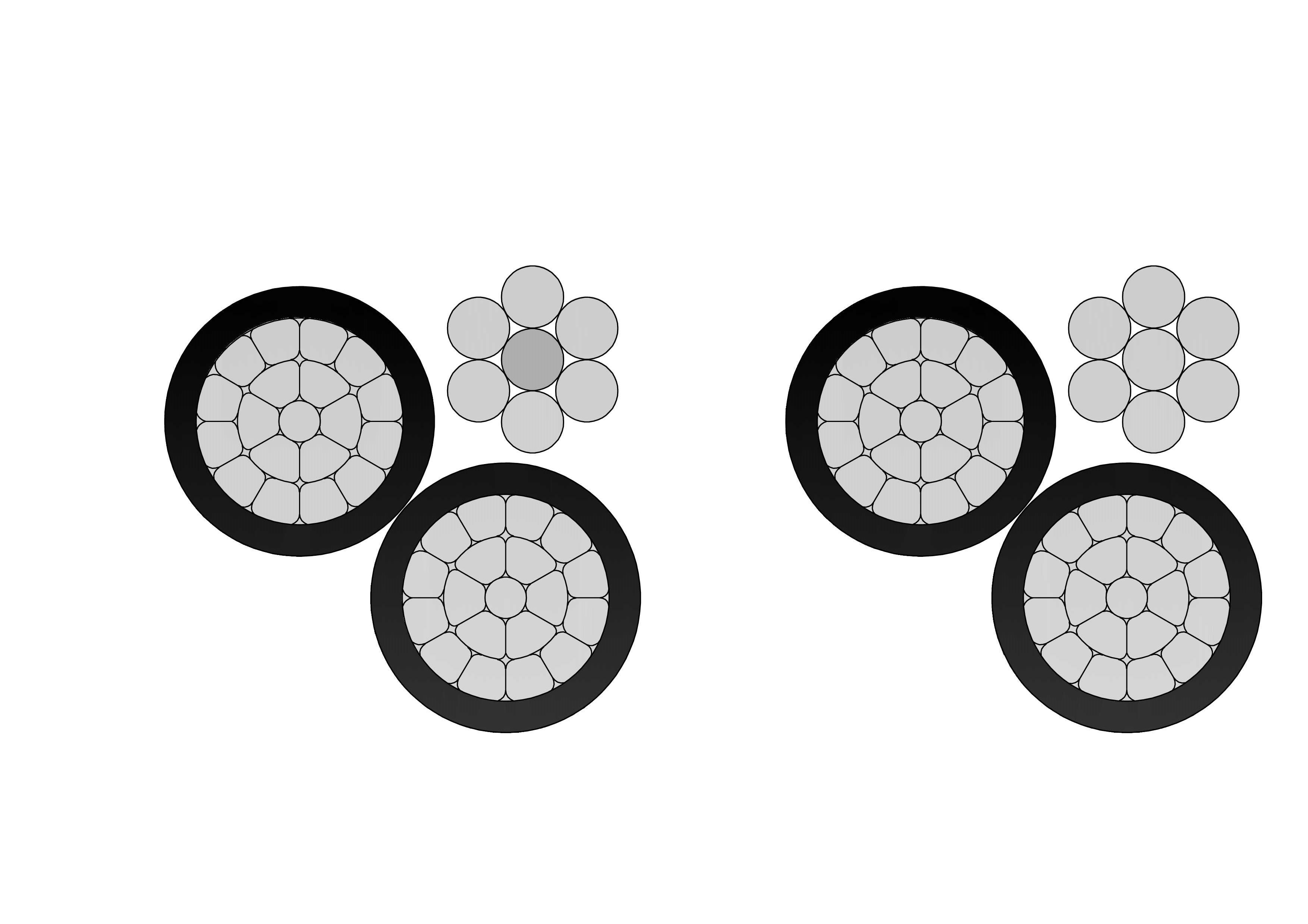
3/0 Fulgar Aluminum Conductor Triplex Overhead Service Drop Cable
3/0 Fulgar Aluminum Conductor Triplex Overhead Service Drop Cable is engineered for high-capacity overhead electrical service connections in utility distribution systems. The cable consists of two insulated aluminum phase conductors twisted around a bare aluminum neutral messenger, ensuring stable electrical transmission and strong mechanical support. Manufactured using high-purity aluminum and weather-resistant insulation compounds, the 3/0 Fulgar Aluminum Conductor Triplex Overhead Service Drop Cable delivers low electrical resistance, excellent corrosion resistance, and reliable long-term performance in outdoor environments. Its optimized conductor design allows efficient installation while maintaining the tensile strength required for aerial service applications. The cable is designed to withstand UV exposure, wind loading, and temperature fluctuations. Comprehensive quality control procedures and systematic testing are applied throughout the manufacturing process to ensure compliance with industry and utility standards and dependable field operation.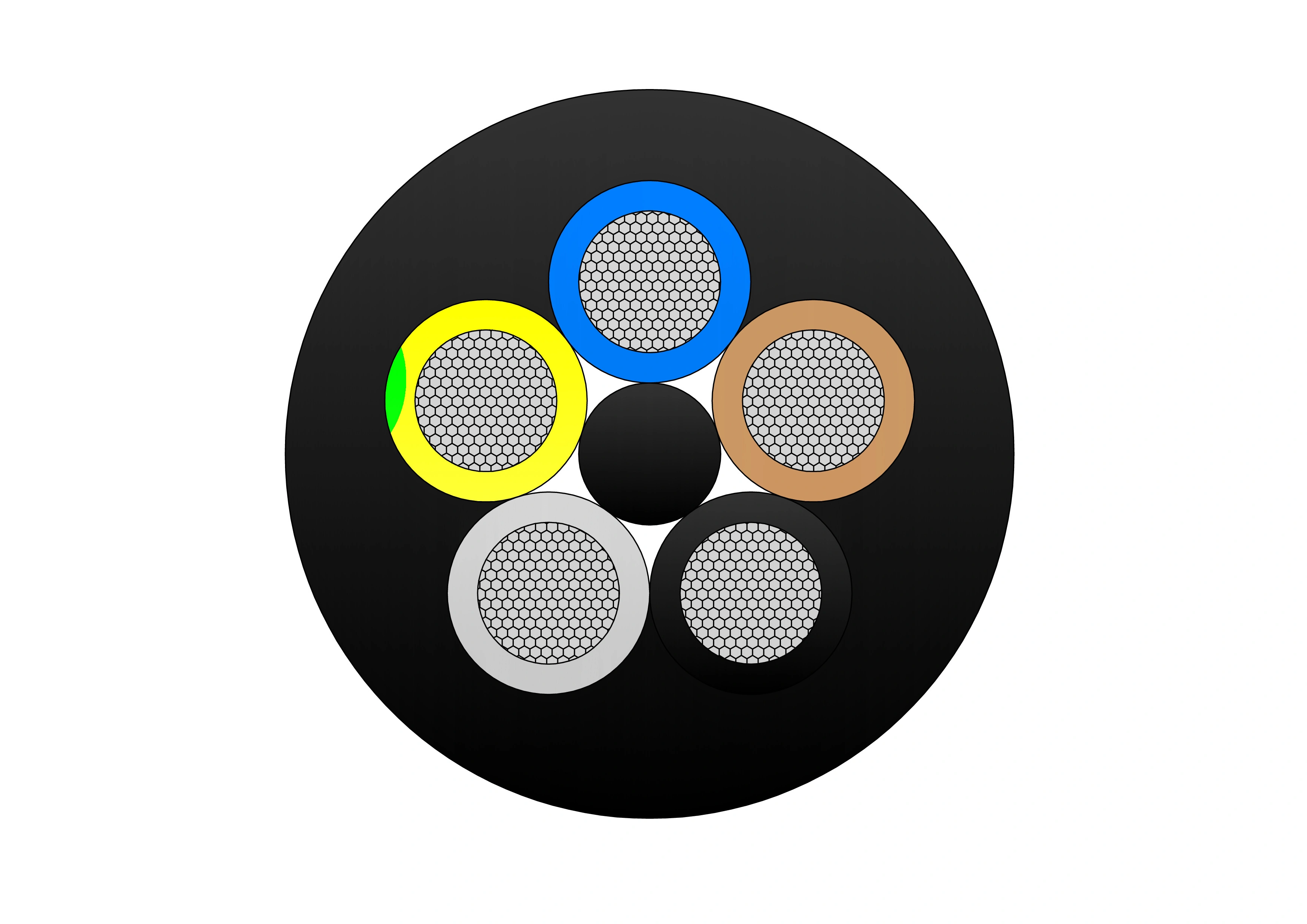
NTSCGECECWOU 3.6/6kV and 6/10kV Cable
The NTSCGECECWOU 3.6/6kV and 6/10kV cable is a flexible medium voltage power cable manufactured to VDE 0250 Part 813 standards, designed for reeling and trailing applications in mining, tunneling, and other demanding industrial environments. Constructed with Class 5 tinned copper conductors, EPR insulation, and a robust halogen-free sheath, it delivers exceptional mechanical strength, flame retardancy, oil resistance, and flexibility. Its copper wire screen ensures EMC protection, while the rugged sheath withstands extreme temperatures, making it suitable for both indoor and outdoor installations in harsh conditions.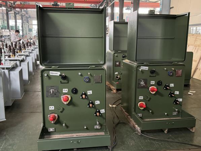
200kVA Single Phase Pole Mounted Transformer
NPC ELECTRIC'S 200kVA single phase pole mounted transformer delivers exceptional reliability for demanding overhead power systems. It efficiently converts primary voltages like 11kV or 22kV to secondary levels such as 220V or 400V, supporting heavier loads in diverse environments. Constructed with low-loss grain-oriented steel cores and high-grade aluminum conductors, it achieves superior energy efficiency and reduced operational costs. Meeting ANSI/IEEE C57 standards, the weatherproof enclosure ensures protection against elements, with a 55°C temperature rise and ONAF cooling for enhanced performance. Essential safety integrations include overload fuses and oil level gauges, making it suitable for utilities aiming for minimal downtime. This transformer excels in providing stable power with low harmonic distortion, ideal for modern grid upgrades.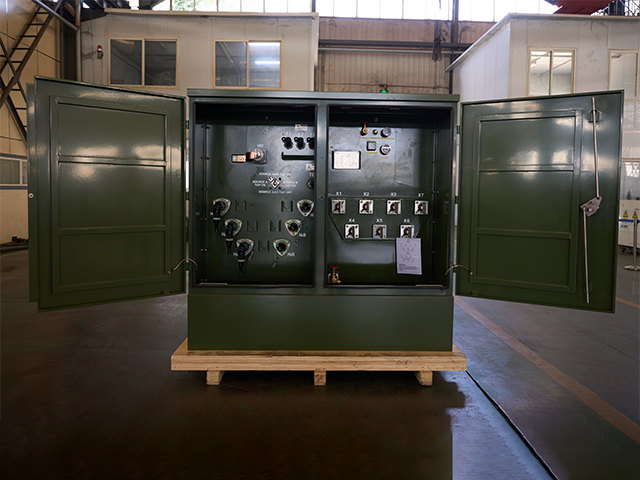
3750kVA Three Phase Pad Mounted Transformer
NPC ELECTRIC's 3750kVA Three Phase Pad Mounted Transformer is a heavy-duty, oil-immersed compartmental-type distribution transformer engineered for high-capacity underground power distribution in large-scale utility and industrial settings. This high-power pad-mounted transformer reduces energy consumption, lowers total ownership costs through superior efficiency and longevity (30+ years), and supports demanding loads with features like vacuum fault interrupters and harmonic mitigation, ideal for reliable, secure power in expansive commercial-industrial networks.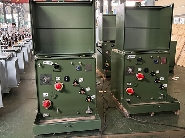
1250kVA Single Phase Pad Mounted Transformer
The 1250kVA Single Phase Pad Mounted Transformer is a premium solution crafted for expansive underground electrical systems in high-growth areas. Housed in a secure, weatherproof cabinet with advanced dead-front or live-front configurations, it maximizes personnel safety and deters tampering in public spaces. Adhering to ANSI C57.12.25, IEEE C57.12.91, and energy efficiency mandates, this 1250kVA single-phase padmount excels in transforming primary voltages up to 34.5kV to flexible secondary levels, offering exceptional short-circuit strength and quiet operation for large-scale residential and commercial deployments.
1600kVA Single Phase Pad Mounted Transformer
The 1600kVA Single Phase Pad Mounted Transformer represents the pinnacle of high-capacity underground distribution technology, engineered to handle the most demanding residential and commercial loads with outstanding efficiency and longevity. Conforming to the latest ANSI C57.12.38, IEEE C57.12.00, and DOE 2016/2020 efficiency tiers, this 1600kVA single-phase padmount provides reliable step-down from primary voltages up to 46kV to versatile secondary configurations, supporting massive loop-feed networks with superior overload tolerance and virtually silent operation.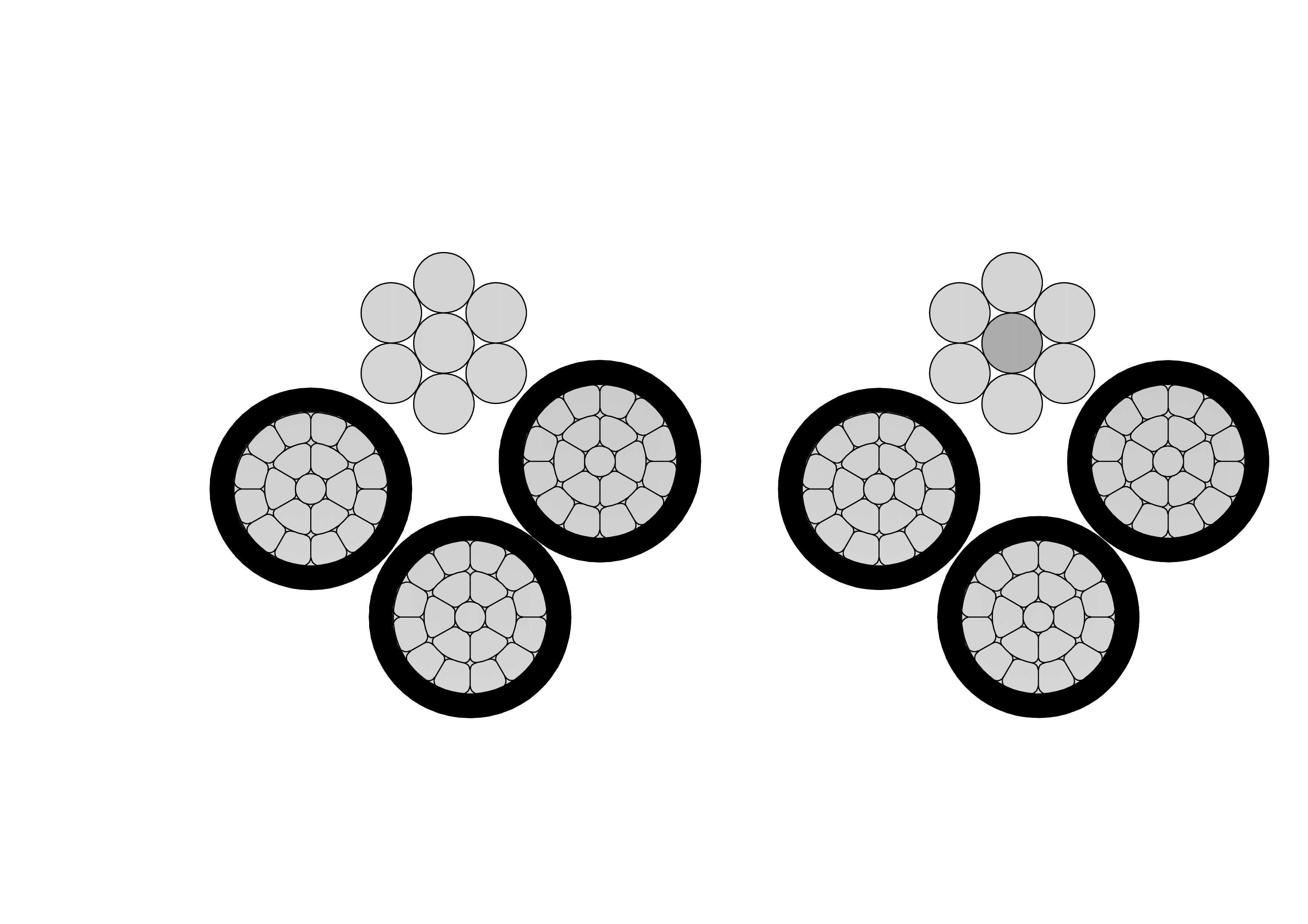
3/0 Suffolk Aluminum Conductor Quadruplex Overhead Service Drop Cable
The 3/0 Suffolk Quadruplex Service Drop Cable is a robust overhead cable for three-phase secondary power distribution with neutral. Featuring three 3/0 AWG aluminum phase conductors and one neutral messenger (7-strand) insulated with XLPE or PE and assembled in quadruplex configuration, it offers excellent mechanical strength and weather resistance. Compliant with ASTM B-230, B-231, ICEA S-76-474, and ANSI/ICEA standards, this cable supports 600V applications with superior UV, moisture, and abrasion protection. The self-supporting messenger reduces sag and simplifies installation over medium spans. The 3/0 Suffolk Quadruplex Service Drop Cable ensures low power losses, high current capacity, and long service life in harsh outdoor conditions. Lightweight and flexible, it is widely used for three-phase service drops in residential subdivisions, commercial buildings, and rural areas requiring safe, cost-effective aerial connections from utility poles to service entrances.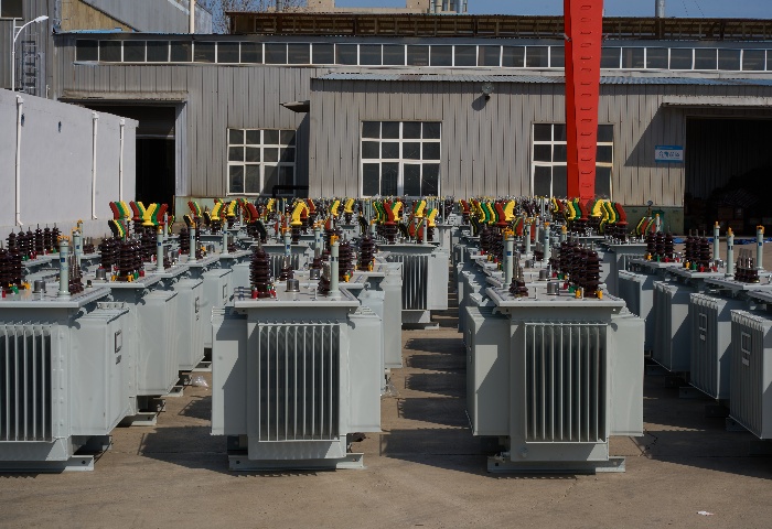
450kVA Oil Immersed Transformer
The 450kVA Oil Immersed Transformer is a reliable three-phase distribution transformer engineered for medium-voltage step-down applications in 50/60Hz AC systems, typically with primary voltages of 11kV or 33kV (options for 6kV/10kV/20kV) and secondary at 0.4kV/0.415kV/0.433kV. High-grade cold-rolled grain-oriented silicon steel core with low-loss lamination reduces no-load losses, while copper or aluminum windings paired with premium mineral oil minimize load losses and enable ONAN cooling for strong overload capacity. Compliant with IEC 60076, GB/T6451, and energy efficiency standards (e.g., S11/S13 series), it achieves high overall efficiency (>98-99%) at typical loads, low noise (<55dB), and reduced total ownership costs for residential, commercial, and light industrial power distribution.
350kVA Epoxy Resin Cast Dry Type Transformer 3 Phase 6.6kV/0.4kV Low Noise
Presenting the high-performance 350kVA Epoxy Resin Cast Dry Type Transformer 3 Phase 6.6kV/0.4kV Low Noise, a cutting-edge, eco-friendly power distribution solution ideal for indoor applications demanding superior safety and quiet operation. This three-phase dry-type transformer utilizes premium epoxy resin vacuum casting on high-conductivity copper windings and low-loss grain-oriented silicon steel cores, achieving outstanding energy efficiency (typically 98%+), minimal no-load/load losses, and exceptional partial discharge suppression (<10pC). With natural air (AN) cooling, Class F/H insulation, fire-retardant self-extinguishing properties, and robust short-circuit withstand, it offers maintenance-free reliability in harsh or sensitive environments. Fully compliant with IEC 60076-11, this compact unit steps down 6.6kV primary (with ±2×2.5% off-circuit taps) to 0.4kV secondary (Dyn11 vector group), supporting sustainable grids with overload capability and zero oil risks.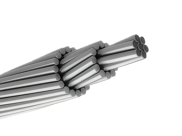
477 MCM HAWK ACSR Conductor Cable
The 477 MCM HAWK ACSR Conductor Cable is a robust and highly efficient Aluminium Conductor Steel Reinforced (ACSR) cable engineered for overhead transmission and distribution networks. It consists of 26 hard-drawn 1350-H19 aluminium wires concentrically stranded around 7 galvanized steel wires, delivering an optimal blend of electrical conductivity and mechanical strength. Designed and manufactured in accordance with ASTM B232, the HAWK configuration is well-suited for long-span overhead lines, where elevated tensile performance is required to withstand environmental loads like wind and ice. The galvanized steel core, available in Class A or B, offers superior corrosion resistance, while the aluminium strands ensure high current-carrying capacity with low resistivity. This conductor is a popular choice in transmission infrastructure due to its balance of strength, weight, and performance, making it a cost-effective and reliable solution in a wide range of operating environments.
Type 275 Flexible Overall Semi-conductive Rubber Screened Mining Cable
The Type 275 Flexible Overall Semi-conductive Rubber Screened Mining Cable is a 1.1kV, medium-voltage cable designed for coal mining and heavy-duty industrial applications. It features tinned annealed copper conductors, EPR insulation, and a semi-conductive thermosetting compound screen for enhanced electrical performance. The cable is reinforced with polyamide yarn braid and protected by a heavy-duty CSP sheath, offering oil resistance, flame retardancy, and mechanical durability. Its robust construction ensures reliable power delivery to shuttle cars, electric pumps, and other mining equipment. Compliant with AS/NZS 2802 and stringent mining standards, it supports very high tensile loads, frequent flexing, tight bending radii, and reliable operation in wet, dusty, and hazardous mine environments.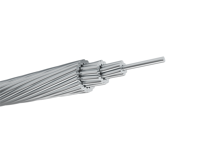
CAIRO AAAC Conductor Cable
CAIRO AAAC (All Aluminum Alloy Conductor) cables comply with ASTM B399 standards and offer high tensile strength, good conductivity, and resistance to corrosion. Named "Cairo" for its 600 mm² nominal area with 61-strand configuration, it offers superior conductivity (53% IACS) and tensile strength (295 MPa min) compared to ACSR. Made from heat-treated aluminum-magnesium-silicon alloy (6201-T81), this cable provides excellent corrosion resistance, low weight, and reduced sag for longer spans. Compliant with ASTM B398, B399, IEC 61089, and BS EN 50182 standards, it supports voltages up to 33kV with ampacity up to 1000A at 75°C. The homogeneous alloy construction eliminates bimetallic corrosion and ensures uniform mechanical properties. The Cairo AAAC Conductor Cable minimizes line losses, withstands harsh weather, and requires minimal maintenance. Ideal for rural electrification, urban upgrades, and renewable energy integrations, it delivers reliable, cost-effective power in overhead lines worldwide, outperforming traditional conductors in corrosive or coastal environments.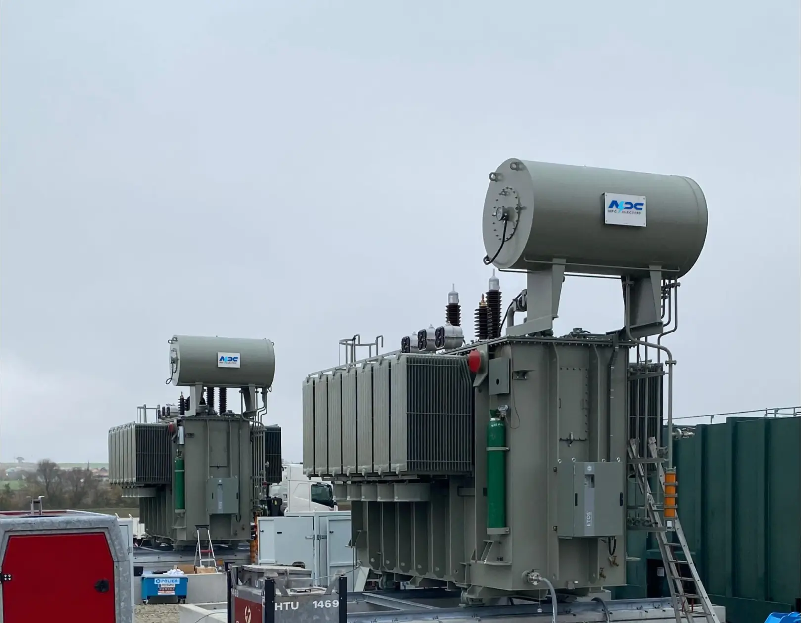
320 kV High Voltage Power Transformer
NPC Electric 320 kV High Voltage Power Transformer is engineered for ultra-high-voltage transmission networks where reliability, efficiency, and operational safety are critical. Designed to handle extreme electrical stress, this transformer supports stable power transfer across long-distance transmission lines and major grid interconnection points. Its oil-immersed insulation system provides superior dielectric strength and efficient heat dissipation, ensuring consistent performance under continuous high-load conditions. Advanced core optimization reduces magnetic losses, while precision winding design enhances voltage regulation and system stability. The transformer structure is built to withstand thermal expansion, mechanical forces, and short-circuit events, making it suitable for demanding grid environments. With long service life, low maintenance requirements, and high operational efficiency, the 320 kV power transformer is an ideal solution for modern high-voltage substations and large-scale energy infrastructure projects.Welcome your inquiry
Honesty, Integrity, Frugality, Activeness and Passion